2 front panel serial port (j4), Table 3-4, Front panel serial port (j4) – Artesyn MVME2500 ECC Installation and Use (August 2014) User Manual
Page 47: Controls, leds, and connectors
Controls, LEDs, and Connectors
MVME2500-ECC Installation and Use (6806800N30F)
47
3.4.1.2
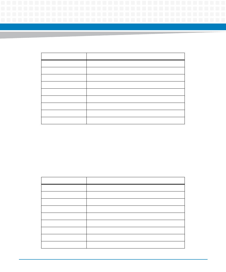
Front Panel Serial Port (J4)
There is one front access asynchronous serial port interface that is routed to the micro mini DB-
9 front panel connector. A male-to-male micro-mini DB9 adapter cable is available under
Artesyn part number SERIAL-MINI-D (30-W2400E01A). The pin assignments for these
connectors are as follows:
6B
Port B TRD2 +
7B
Port B TRD1 -
8B
Port B TRD1 +
9B
Port B TRD0 -
10B
Port B TRD0 +
D1B
Port B Green LED1Anode/ Yellow LED1 Cathode
D2B
Port B Yellow LED1 Anode/ Green LED1 Cathode
D3B
Port B Green LED2Anode/ Yellow LED2 Cathode
D4B
Port B Yellow LED2 Anode/ Green LED2 Cathode
Table 3-3 Front Panel Tri-Speed Ethernet Connector (J1) (continued)
Pin Name
Signal Description
Table 3-4 Front Panel Serial Port (J4)
Pin
Signal Description
1
NC
2
RX
3
TX
4
NC
5
GND
6
NC
7
RTS
8
CTS
9
NC