1 reset switch, 3 leds, 1 front panel leds – Artesyn MVME2500 ECC Installation and Use (August 2014) User Manual
Page 43: Figure 3-3, Front panel leds
Controls, LEDs, and Connectors
MVME2500-ECC Installation and Use (6806800N30F)
43
3.2.1
Reset Switch
The MVME2500-ECC has a single push button switch that has both the abort and reset
functions. Pressing the switch for less than three seconds generates an abort interrupt to the
P20x0 QorIQ PIC. Holding it down for more than three seconds will generate a hard reset. The
VME SYSRESET is generated if the MVME2500-ECC is the VMEbus system controller.
3.3
LEDs
The MVME2500-ECC utilizes light emitting diodes (LEDs) to provide a visible status indicator on
the front panel. These LEDs show power failures, power up states, Ethernet link/speed,
ethernet activity, SATA link and activity and PCI-E valid lane status. There are also a few user
configurable LEDs. Each LED description is necessary for troubleshooting and debugging.
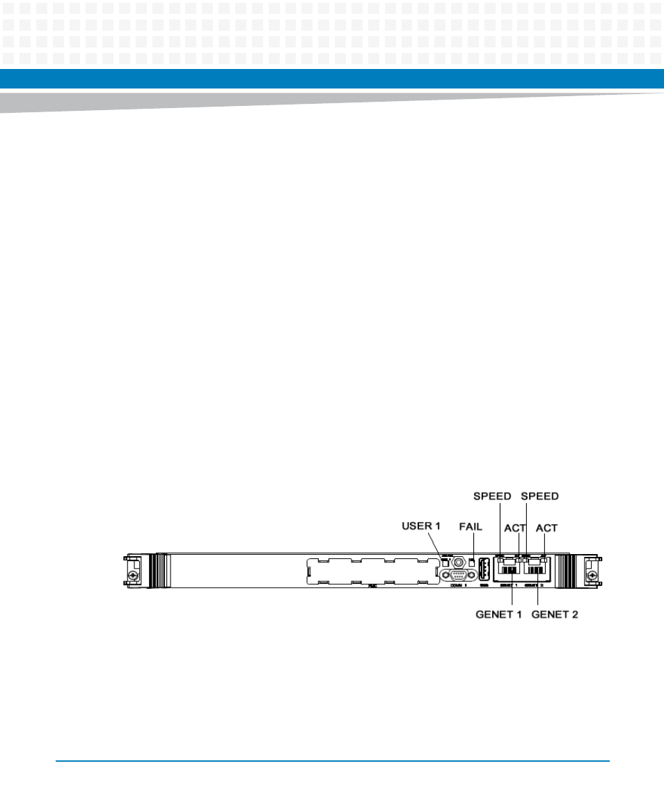
3.3.1
Front Panel LEDs
The front panel LEDs are listed below.
Figure 3-3
Front Panel LEDs