7 xmc connector (xj2), Table 3-17, Xmc connector (xj2) pinout – Artesyn MVME2500 ECC Installation and Use (August 2014) User Manual
Page 61: Controls, leds, and connectors
Controls, LEDs, and Connectors
MVME2500-ECC Installation and Use (6806800N30F)
61
3.4.2.7
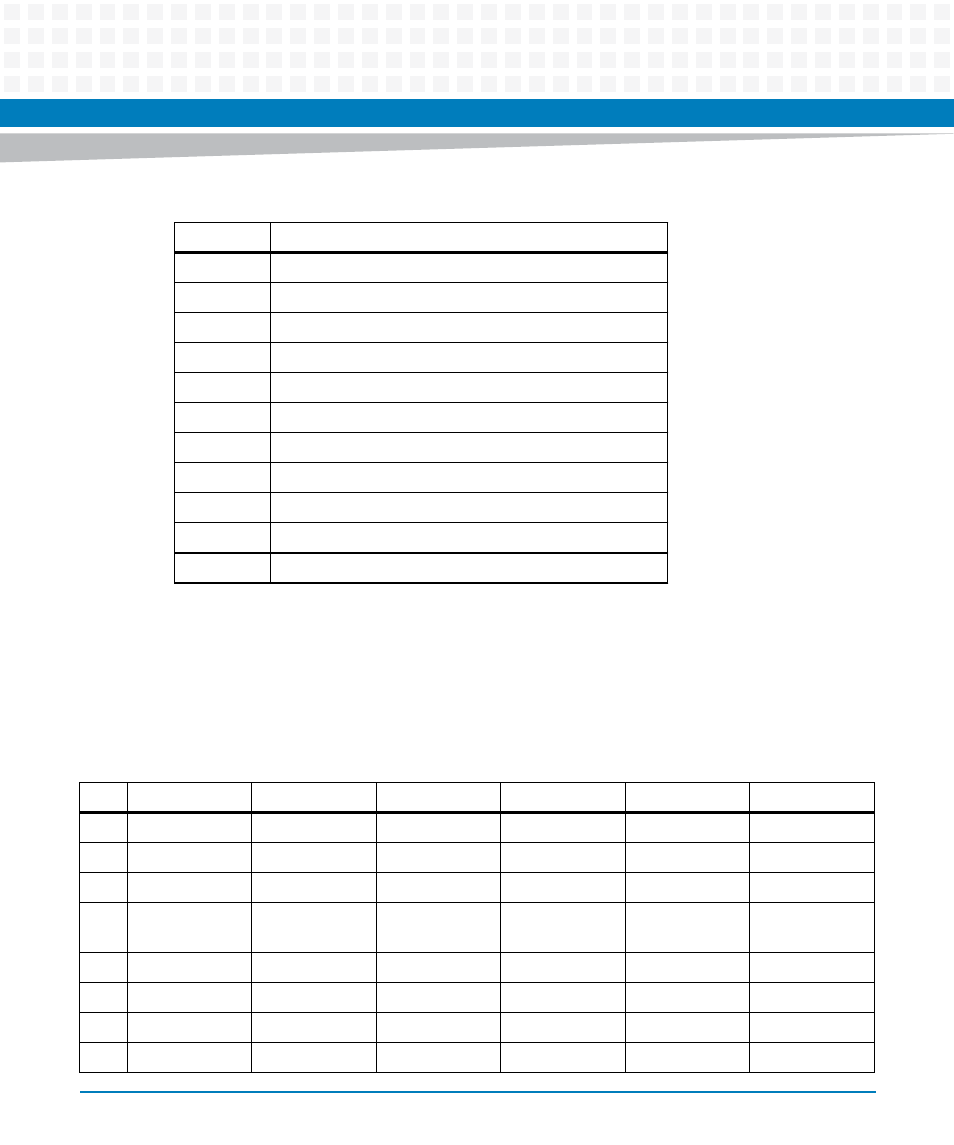
XMC Connector (XJ2)
The MVME2500-ECC has one XMC connector (XJ2) that supports XMC cards with J15
connector. It can also support XMC cards with J16 connector without encountering any
mechanical interference.
2
COMMAND
3
GND
4
VCC (+3.3V)
5
CLOCK
6
GND
7
DATA 0
8
DATA 1
9
DATA 2
10
WRITE PROTECT
11
CARD DETECT
12
GND
Table 3-16 SD Connector (J2) (continued)
Pin
Signal Description
Table 3-17 XMC Connector (XJ2) Pinout
Pin
Row A
Row B
Row C
Row D
Row E
Row F
1
RX0 +
RX0 -
+3.3V
RX1+
RX1 -
+3.3V
2
GND
GND
JTAG TRST
GND
GND
HRESET
3
NC
NC
+3.3V
NC
NC
+3.3V
4
GND
GND
JTAG TCK
GND
GND
MRSTO
(PULLED UP)
5
NC
NC
+3.3V
NC
NC
+3.3V
6
GND
GND
JTAG TMS
GND
GND
+12V
7
NC
NC
+3.3V
NC
NC
+3.3V
8
GND
GND
JTAG TMS
GND
GND
-12V