2 onboard connectors, 1 flash program connector (p7), Table 3-8 – Artesyn MVME2500 ECC Installation and Use (August 2014) User Manual
Page 51: Flash programming header (p7), Controls, leds, and connectors
Controls, LEDs, and Connectors
MVME2500-ECC Installation and Use (6806800N30F)
51
3.4.2
Onboard Connectors
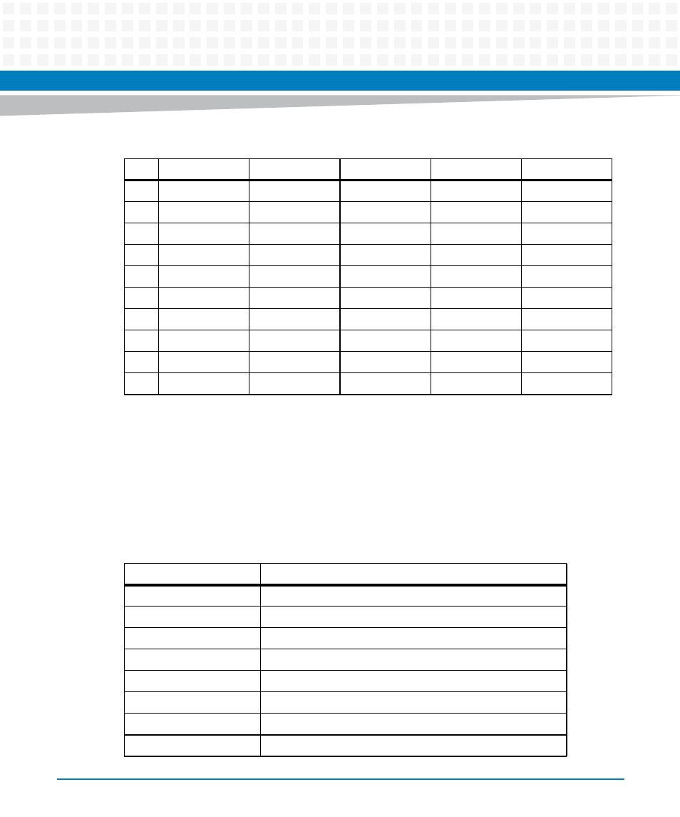
3.4.2.1
Flash Program Connector (P7)
The Flash Program Connector is depopulated in the production version of the MVME2500-ECC.
However, each pin is exposed for the 60-pin header connector for the JTAG boundary scan.
23
PMC IO 46
DATA 24
PMC IO 45
GE4_2 -
Serial 3 RTS
24
PMC IO 48
DATA 25
PMC IO 47
GE4_2+
GND
25
PMC IO 50
DATA 26
PMC IO 49
GND
Serial 4 RX
26
PMC IO 52
DATA 27
PMC IO 51
GE4_1 -
GND
27
PMC IO 54
DATA 28
PMC IO 53
GE4_1 +
Serial 4 TX
28
PMC IO 56
DATA 29
PMC IO 55
GND
GND
29
PMC IO 58
DATA 30
PMC IO 57
GE4_0 -
Serial 4 CTS
30
PMC IO 60
DATA 31
PMC IO 59
GE4_0 +
GND
31
PMC IO 62
GND
PMC IO 61
GND
Serial 4 RTS
32
PMC IO 64
+5V
PMC IO 63
+5V
GND
Table 3-7 VMEbus P2 Connector (continued)
Pin
Row A
Row B
Row C
Row D
Row Z
Table 3-8 Flash Programming Header (P7)
Pin
Signal Description
1
HOLD 1
2
Chip Select 1
3
Chip Select 0
4
Programmer's VCC
5
Master In Slave OUT (MISO)
6
HOLD 0
7
Keying
8
CLOCK