Introduction – Artesyn MVME2500 ECC Installation and Use (August 2014) User Manual
Page 20
Introduction
MVME2500-ECC Installation and Use (6806800N30F)
20
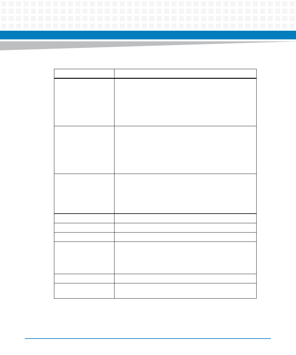
Front panel I/O
Micro DB9 RS-232 serial console port
USB 2.0
Two RJ45 10/100/1000BASE-T Ethernet
Reset/Abort switch
Fail LED and User LED
PMC/XMC front panel I/O (optional)
Backplane I/O
VME Bus
RTM I/O (through VME P2)
PMC/XMC I/O with P4 I/O
Two 10/100/1000BASE-T Ethernet
Four UART
RTM I2C/Presence/Power
Expansion
Expansion site 1:
PMC supporting PCI-X 64/33 interface
XMC supporting PCI-E 1.0a x2 interface
Expansion site 2:
SATA drive kit
Boot Flash
16 MB SPI Flash
Persistent Data Storage
512 KB MRAM
User Flash
SDHC Socket
I2C Devices
Real-Time Clock
Board Temperature Sensor
8 KB VPD EEPROM
Two 64 KB User EEPROM
CPLD
Watchdog, timers, and registers
Boot Firmware
U-Boot-based firmware image in 16 MB SPI Flash. This flash is split
into two 8 MB chips.
Table 1-1 Key Features of the MVME2500-ECC (continued)
Function
Features