2 control registers, Table 5-22, Control registers – Artesyn MVME2500 ECC Installation and Use (August 2014) User Manual
Page 105
Memory Maps and Registers
MVME2500-ECC Installation and Use (6806800N30F)
105
5.5.2
Control Registers
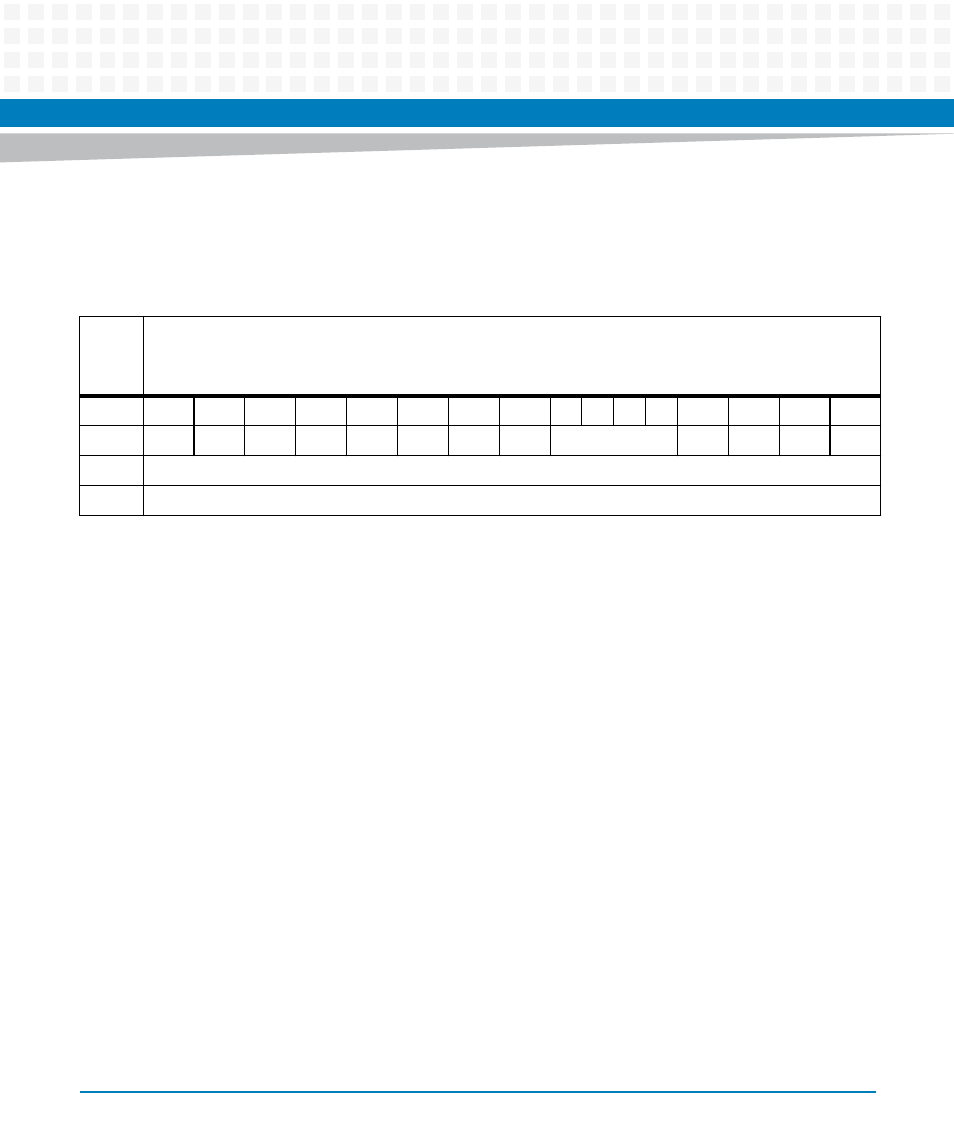
Table 5-22 Control Registers
REG
Tick Timer 0 Control Register - 0xFFC80202
Tick Timer 1 Control Register - 0xFFC80302
Tick Timer 2 Control Register - 0xFFC80402
Bit
15
14
13
12
11
10
9
8
7
6
5
4
3
2
1
0
Field
RSVD
RSVD
RSVD
RSVD
RSVD
INTS
CINT
ENINT
OVF
RSVD
COVF
COC
ENC
OPER
R/W
RESET
0x0000
Field Description
ENC
Enable counter. When the bit is set, the counter increments. When the bit is
cleared, the counter does not increment.
COC
Clear Counter on Compare. When the bit is set, the counter is reset to 0 when
it compares with the compare register. When the bit is cleared the counter is
not reset.
COVF
Clear Overflow Bits. The overflow counter is cleared when a 1 is written to this
bit.
OVF
Overflow Bits are the output of the overflow counter. It increments each time
the tick timer sends an interrupt to the local bus interrupter. The overflow
counter can be cleared by writing a 1 to the COVF bit.
ENINT
Enable Interrupt. When the bit is set, the interrupt is enabled. When the bit is
cleared, the interrupt is not enabled.
CINT Clear
Interrupt.
INTS Interrupt
Status.
RSVD
Reserved for future implementation.