Table 3-12, Pmc j13 connector, Controls, leds, and connectors – Artesyn MVME2500 ECC Installation and Use (August 2014) User Manual
Page 55
Controls, LEDs, and Connectors
MVME2500-ECC Installation and Use (6806800N30F)
55
10
NC
42
SERR
11
BUSMODE2 (Pulled UP)
43
CBE1
12
+3.3V
44
GND
13
PCI RESET
45
AD 14
14
BUSMODE3 (PULLED DWN)
46
AD 13
15
+3.3V
47
M66EN
16
BUSMODE4 (PULLED DWN)
48
AD 10
17
NC
49
AD 8
18
GND
50
+3.3V
19
AD 30
51
AD 7
20
AD 29
52
REQB
21
GND
53
+3.3V
22
AD 26
54
GNTB
23
AD 24
55
NC
24
+3.3V
56
GND
25
IDSEL
57
NC
26
AD 23
58
EREADY
27
+3.3V
59
GND
28
AD 28
60
RSTOUT
29
AD 18
61
ACK64
30
GND
62
+3.3V
31
AD 16
63
GND
32
CBE2
64
NC
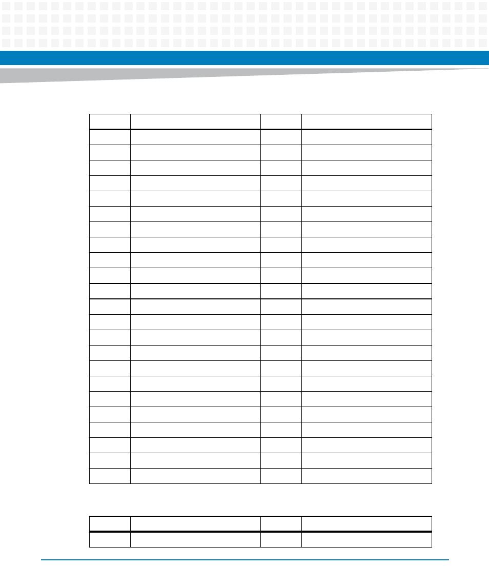
Table 3-12 PMC J13 Connector
Pin
Signal Description
Pin
Signal Description
1
NC
33
GND
Table 3-11 PMC J12 Connector (continued)
Pin
Signal Description
Pin
Signal Description