5 cop connector (p6), 6 sd connector (j2), 5 cop connector (p6) 3.4.2.6 sd connector (j2) – Artesyn MVME2500 ECC Installation and Use (August 2014) User Manual
Page 60: Table 3-15, Cop header (p10), Table 3-16, Sd connector (j2), Controls, leds, and connectors
Controls, LEDs, and Connectors
MVME2500-ECC Installation and Use (6806800N30F)
60
3.4.2.5
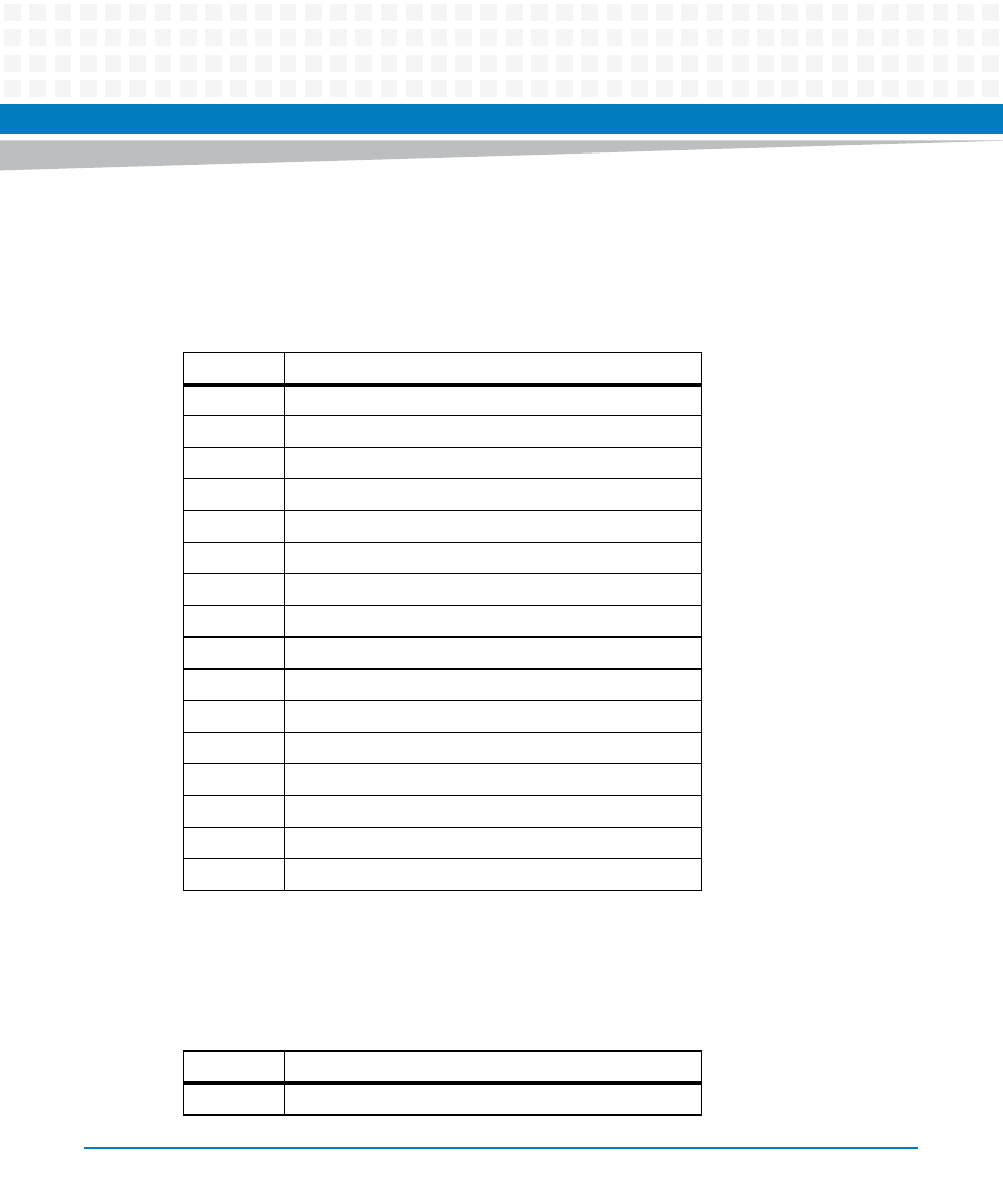
COP Connector (P6)
The COP header is used for the CPU debug. The pin assignment is dictated by Freescale and is
compatible with the processor’s debugging tool.
3.4.2.6
SD Connector (J2)
Table 3-15 COP Header (P10)
Pin
Signal Description
1
JTAG TDI
2
COP QACK
3
JTAG TDO
4
COP TRST
5
COP RUNSTOP (Pulled UP)
6
COP VDD SENSE
7
JTAG TCK
8
COP CHECK STOP IN
9
JTAG TMS
10
NC
11
P2020 SW RESET
12
COP PRESENT
13
COP HARD RESET
14
KEYING
15
COP CHECK STOP OUT
16
GND
Table 3-16 SD Connector (J2)
Pin
Signal Description
1
DATA 3