3 pmc connectors, Table 3-10, Pmc j11 connector – Artesyn MVME2500 ECC Installation and Use (August 2014) User Manual
Page 53: Controls, leds, and connectors
Controls, LEDs, and Connectors
MVME2500-ECC Installation and Use (6806800N30F)
53
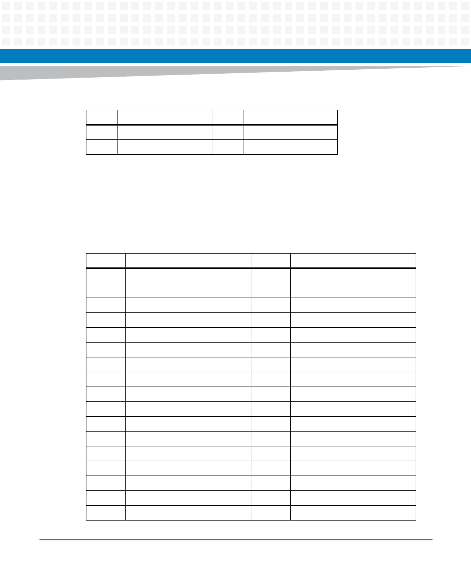
3.4.2.3
PMC Connectors
The MVME2500-ECC supports only one PMC site. It utilizes J14 to support PMC I/O that goes to
the RTM PMC. The tables below show the pinout detail of J11, J12, J13 and J14. See
for the location of the PMC connectors.
19
NC
39
+3.3V
20
GND
40
+5V
Table 3-9 Custom SATA Connector (J3) (continued)
Pin
Signal Description
Pin
Signal Description
Table 3-10 PMC J11 Connector
Pin
Signal Description
Pin
Signal Description
1
JTAG TCK
33
FRAME
2
-12V
34
GND
3
GND
35
GND
4
INT A
36
IRDY
5
INT B
37
DEVSEL
6
INT C
38
+5V
7
PRESENT SIGNAL
39
PCIXCAP
8
+5V
40
LOCK
9
INT D
41
NC
10
NC
42
NC
11
GND
43
PAR
12
NC
44
GND
13
PCI CLK
45
+3.3V
14
GND
46
AD 15
15
GND
47
AD 12
16
GNT A
48
AD 11
17
REQ A
49
AD 9