3 usb connector (j5), 4 vmebus p1 connector, 3 usb connector (j5) 3.4.1.4 vmebus p1 connector – Artesyn MVME2500 ECC Installation and Use (August 2014) User Manual
Page 48: Table 3-5, Usb connector (j5), Table 3-6, Vmebus p1 connector, Controls, leds, and connectors
Controls, LEDs, and Connectors
MVME2500-ECC Installation and Use (6806800N30F)
48
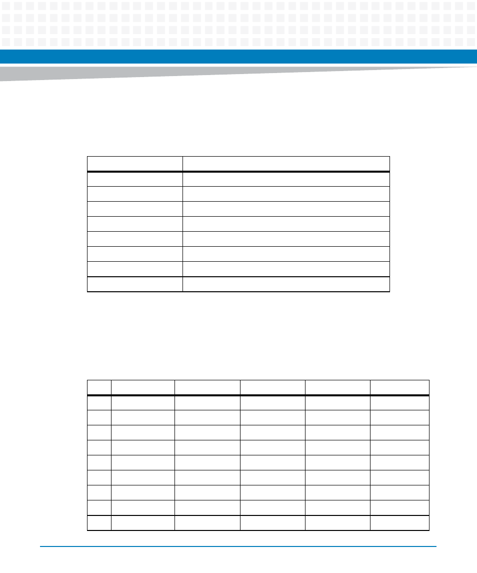
3.4.1.3
USB Connector (J5)
The MVME2500-ECC uses upright USB receptable mounted in the front panel.
3.4.1.4
VMEbus P1 Connector
The VME P1 connector is a 160-pin DIN. The P1 connector provides power and VME signals for
24-bit address and 16-bit data. The pin assignments for the P1 connector is as follows:
Table 3-5 USB Connector (J5)
Pin Name
Signal Description
1
+5 V
2
Data -
3
Data +
4
GND
MTG
Mounting Ground
MTG
Mounting Ground
MTG
Mounting Ground
MTG
Mounting Ground
Table 3-6 VMEbus P1 Connector
Pin
Row A
Row B
Row C
Row D
Row Z
1
DATA 0
BBSY
DATA 8
+5V
NC
2
DATA 1
BCLR
DATA 9
GND
GND
3
DATA 2
ACFAIL
DATA 10
NC
NC
4
DATA 3
BGIN0
DATA 11
NC
GND
5
DATA 4
BGOUT0
DATA 12
NC
NC
6
DATA 5
BGIN1
DATA 13
NC
GND
7
DATA 6
BGOUT1
DATA 14
NC
NC
8
DATA 7
BGIN2
DATA 15
NC
GND
9
GND
BGOUT2
GND
GAP
NC