10 clock and lock mode (-lkm/-lks option) – AMETEK Compact i/iX Series User Manual
Page 49
User Manual
Compact i/iX Series
AMETEK Programmable Power
California Instruments
49
3.10 Clock and Lock Mode (-LKM/-LKS Option)
Clock and lock mode operation of two or more iX AC power sources is available only if the
–LKM and –
LKS options have been installed at the factory. With these options installed, it is possible to lock an
auxiliary unit (-LKS) to a master unit (-LKM). The master unit controls the frequency. This configuration
can be used to create multiphase power systems such as split-phase or three phases. The auxiliary
unit must be set to external clock mode from the Control screen. See section 4.2.5.
Two BNC connectors are provided on the rear panel of the iX model for clock and lock mode. Both
need to be connected between the master and auxiliary unit. On the master unit (-LKM), both are
outputs. On the auxiliary unit (-
LKS), both are inputs. Do not connect these BNC’s between two master
units (-
LKM’s) or damage to the unit could result.
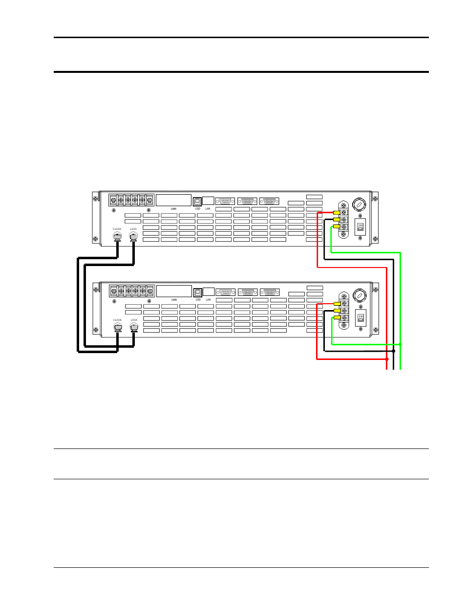
Master power source (-LKM)
Auxiliary power source (-LKS)
L N Gnd
AC Line
CLOCK
LOCK
Figure 3-8: Clock and Lock Connections
Refer to Figure 3-8 for the required connections between the
–LKM and –LKS units. (Shown for Series
I but similar for Series II models). The example is shown for two units, one master, one auxiliary. More
than one auxiliary can be used to create additional phase outputs. In this case, the BNC cables can be
daisy chained using BNC T connectors.
WARNING:
DO NOT CONNECT THE AC OUTPUTS OF THE
–LKM AND –LKS UNITS TOGETHER.
CLOCK AND LOCK OUTPUTS CANNOT BE PARALLELED TO OBTAIN HIGHER OUTPUT
CURRENTS.
Do not use clock and lock mode to obtain higher power capability on the same phase(s). For higher
power configurations, use the multi-chassis configuration through the system interface connection
instead. Refer to section 0 for multi-chassis configuration and connection information.
The frequency of the auxiliary unit will track that of the master. The output phase angle of phase 1/A
will be locked to the auxiliary unit as well to within 3°. This allows split phase or multi-phase
configurations to be created.