AMETEK Compact i/iX Series User Manual
Page 48
User Manual
Compact i/iX Series
AMETEK Programmable Power
California Instruments
48
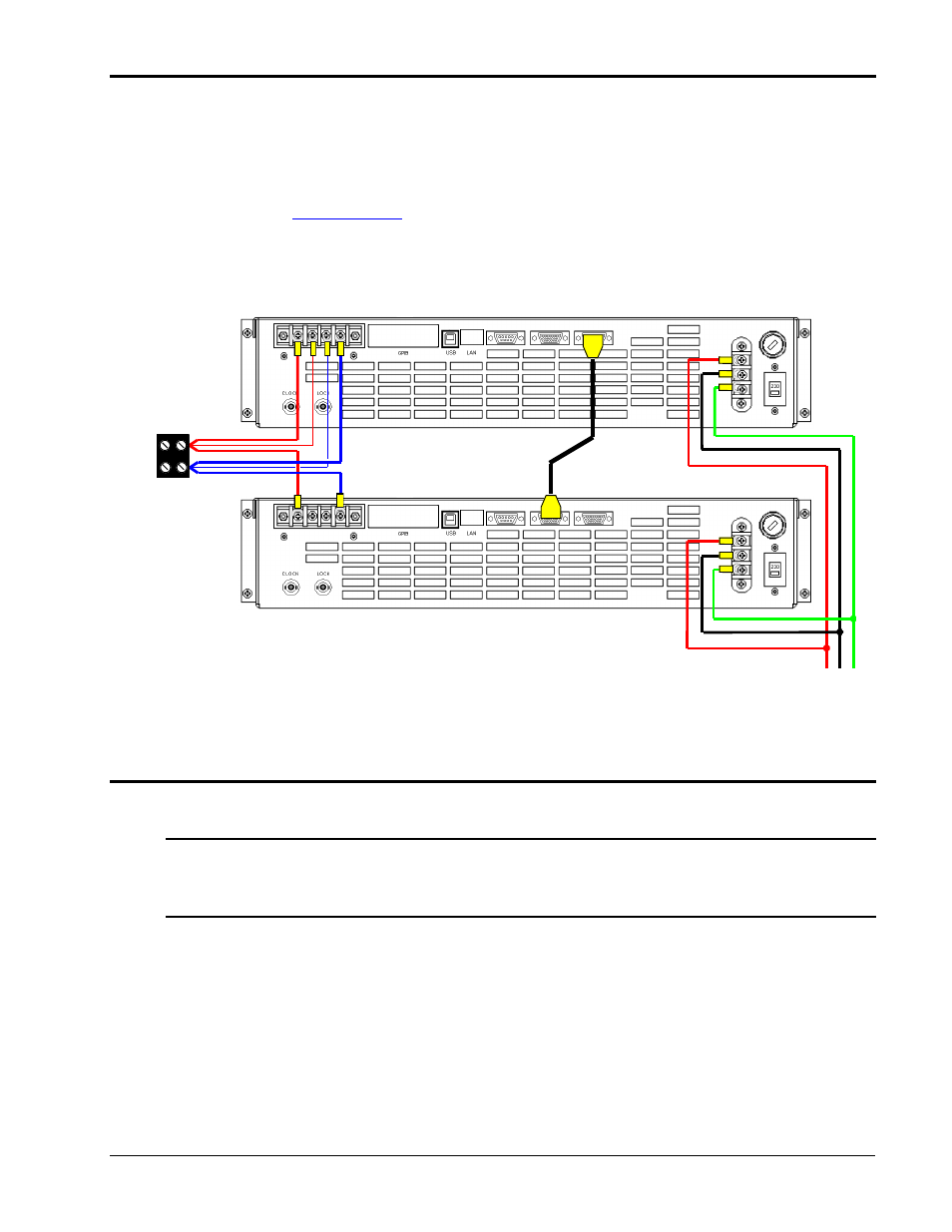
Multi-chassis Output Wiring Diagram
Figure 3-7 shows the required output connections for a two chassis system (rear-view perspective).
Always turn off both the Master and Auxiliary power source before making or changing output
connections. The terminal block shown to connect the outputs of both chassis together is provided in
the ship kit. The System Interface cable is a high density HD15 to HD15 M/F cable approximately 1.5
meters in length.
/N CHD15MF-5). This cable connects between the male DB15
connector on the Master unit rear panel labeled TO AUXILIARY and the female DB15 connector on the
Auxiliary unit rear panel labeled TO MASTER as shown in Figure 3-7. (Shown for Series I but similar
for Series II models).
L N Gnd
AC Line
Master power source
Auxiliary power source
System
Interface
Cable
To
Load
Junction
Block
Equal length
output wires
Output High
Output Low
Figure 3-7: 3001iX/2 Output Wiring
3.9.1 Power Up and Power Down sequence.
A multi-box i/iX system can be turned on in either order.
Note: It is not recommended to turn off either unit without turning off the other unit and then
turning it back on. This may result in miscellaneous error messages occurring on the
unit that was not powered down. If one unit has been turned off, turn off all units first
before turning the system back on.
If a master unit is to be used by itself, it is not sufficient to just leave the auxiliary unit off while the
system interface cable remains connected. Disconnect the system interface from the back of the
master unit and then turn the unit on for stand-alone use. It is also necessary to reconfigure the system
configuration in the CONFIGURATION menu, section 4.2.9.