AMETEK Compact i/iX Series User Manual
Page 38
User Manual
Compact i/iX Series
AMETEK Programmable Power
California Instruments
38
3.6.2 Output Terminal Block - OUTPUT
Each chassis has a single AC output terminal block. The output terminal block must be covered using
the supplied AC Output safety cover. The terminal blocks are large enough to accommodate required
wire gauge sizes. The terminal block is located in the upper left corner on the rear panel of the unit.
(Looking from the back). Connector type is Magnum, A307104R50.
The AC output terminal strip accommodates a #6 ring or spade lug. The use of sleeved ring lugs
(12/10-6 Yellow sleeve lug) or compressed cable lug for the load carrying output wiring is
recommended.
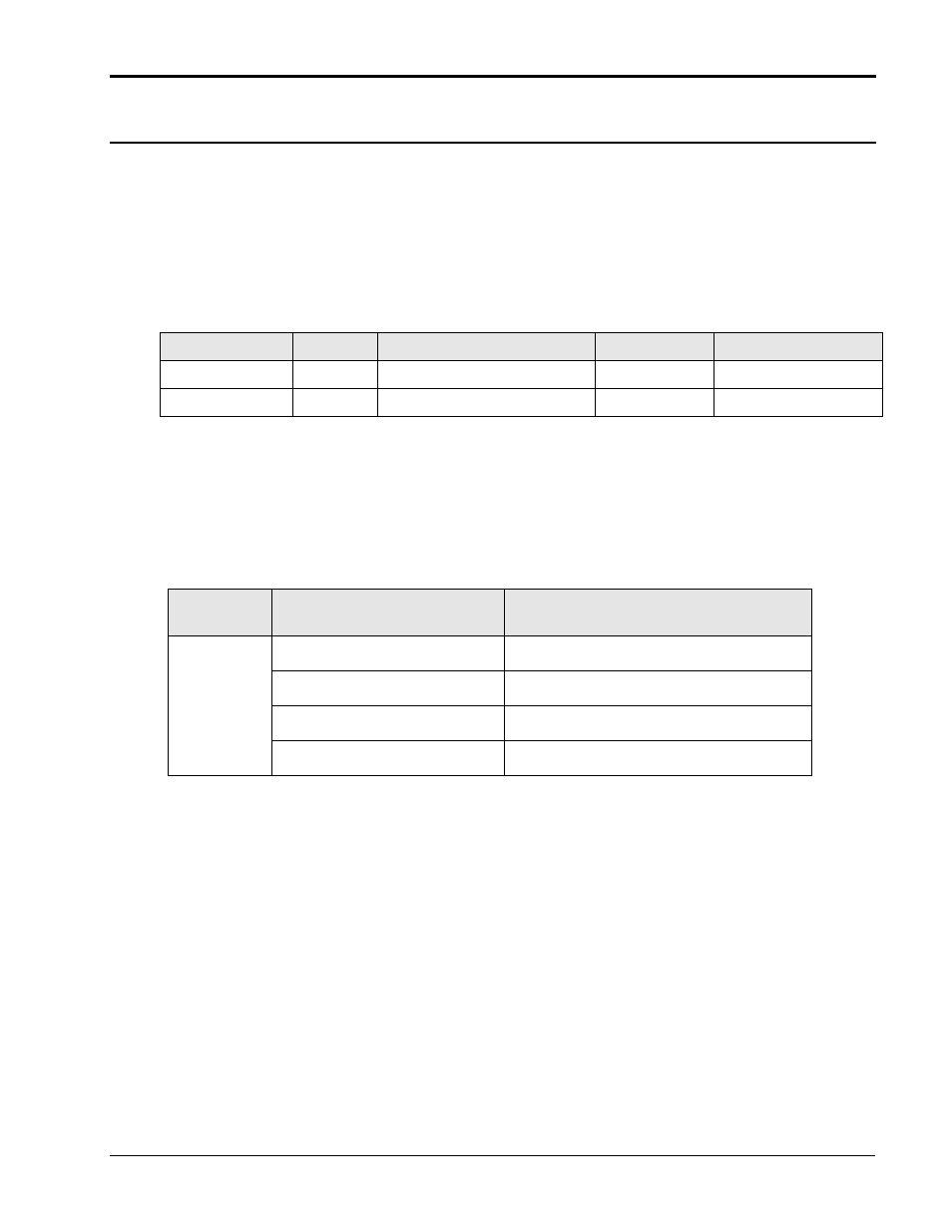
Following output terminal lugs are included in i/iX ship kit:
Use
CI P/N
Description
Qty supplied
For use with:
OUTPUT (TB2)
FS2004
Ring Lug 12/10-6
2
Output Hi, Output Lo
SENSE (TB2)
FS2002
Ring Lug 22/18-6
2
Sense Hi, Sense Lo
Multi-chassis configurations have two output terminal blocks, one on the master chassis and one of the
auxiliary chassis.
For operation as a multi-chassis system, the outputs of all chassis must be connected together using
the additional terminal blocks provided in the ship kit. Keep the wire lengths between each chassis
and this common terminal block the same.
See Figure 3-7 for multi-chassis output wiring diagram.
Connector
TB1
Terminal
Output
1
Output High
2
Sense High
3
Sense Low
4
Output Low
Table 3-1: Output Terminal connections.