Altera Floating-Point User Manual
Page 89
ALTFP_INV_SQRT Design Example: Understanding the Simulation Results
The simulation waveform in this design example is not shown in its entirety. Run the design example files
in the ModelSim-Altera software to see the complete simulation waveforms.
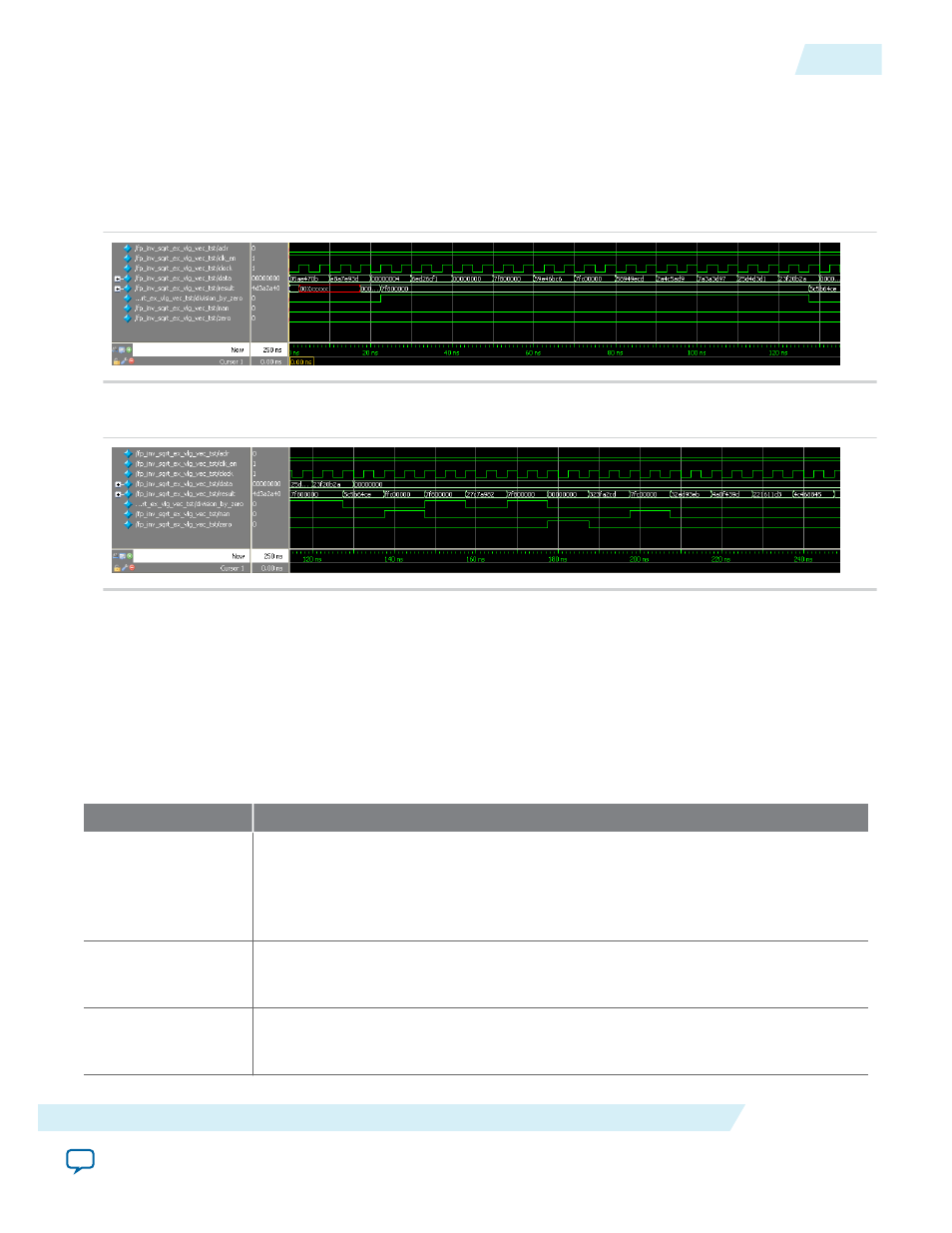
These figures show the expected simulation results in the ModelSim-Altera software.
Figure 11-1: ALTFP_INV_SQRT ModelSim Simulation Waveform (Input Data)
Figure 11-2: ALTFP_INV_SQRT ModelSim Simulation Waveform (Output Data)
This design example implements a floating-point inverse square root for single-precision format
numbers. The optional input ports (
clk_en
and
aclr
) and all three exception handling output ports
(
division_by_zero
,
nan
, and
zero
) are enabled.
The latency is fixed at 26 clock cycles. Therefore, every inverse square root operation outputs the results
26 clock cycles later.
This table lists the inputs and corresponding outputs obtained from the simulation in the waveforms.
Table 11-4: Summary of Input Values and Corresponding Outputs
Time
Event
0 ns, start-up
data[]
value: 05AE 470Bh
Output value: An undefined value is seen on the
result[]
port, which can be
ignored. All values seen on the output port before the 26th clock cycle are merely
due to the behavior of the system during start-up and should be disregarded.
127.5 ns
Output value: 5C5B 64CEh
The inverse square root of a normal number results in a normal value.
10 ns
data[]
value: E8A7 E93Dh
This is a negative normal value.
UG-01058
2014.12.19
ALTFP_INV_SQRT Design Example: Understanding the Simulation Results
11-3
ALTFP_INV_SQRT IP Core
Altera Corporation