Altera Floating-Point User Manual
Page 31
ALTERA_FP_MATRIX_INV Design Example: Understanding the Simulation Results
The simulation waveform in this design example is not shown in its entirety. Run the design example files
in the ModelSim-Altera software to see the complete simulation waveforms.
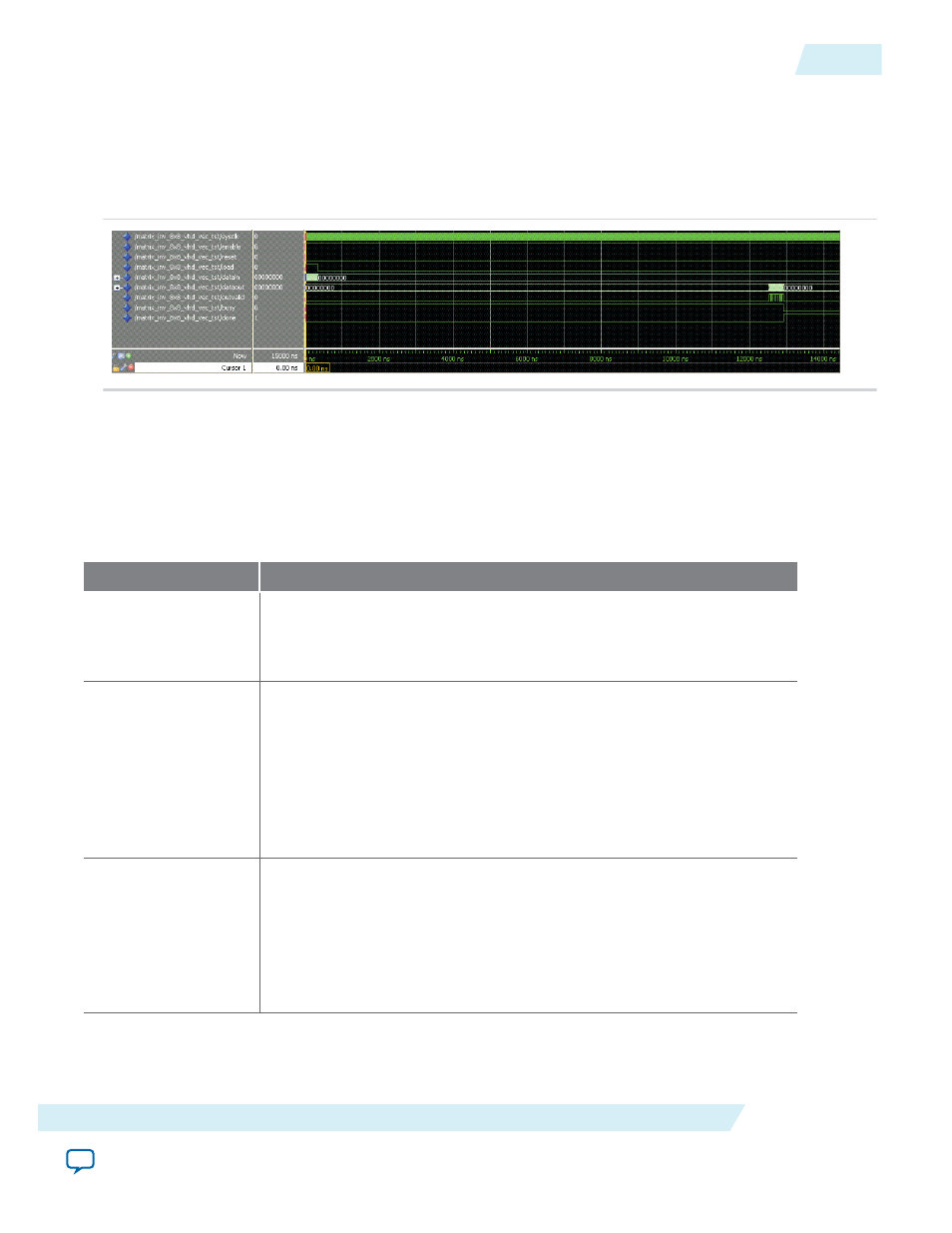
Figure 2-4: ALTERA_FP_MATRIX_INV ModelSim Simulation Waveform (Input Data)
This figure shows the expected simulation results in the ModelSim-Altera software.
This design example implements a floating-point matrix inversion to calculate the inverse value of
matrices in single-precision formats. The optional input ports (
enable
and
reset
) are enabled.
Table 2-2: Summary of Input Values and Corresponding Outputs
This table lists the inputs and corresponding outputs obtained from the simulation waveform. The number of
clock cycles obtained for each stage is based on the particular matrix size and parameter settings used in this
design example.
Time
Event
0 ns – 10 ns
Start sequence:
• The
reset
signal deasserts.
• The
enable
signal asserts.
19.86 ns – 340 ns
Matrix input data load:
• The
load
signal asserts and remains high for 80 clock cycles.
• As long as the
load
signal is high, data for the input matrix is loaded
row by row.
• Input data is burst in regularly, one at every clock cycle.
• The
load
signal deasserts at 340 ns. The deassertion of the
load
signal
signifies the completion of the data load operation for the matrix.
27.5 ns
Processing stage:
• The
busy
signal asserts while the
done
signal deasserts.
• The assertion of the
busy
signal and the deassertion of the
done
signal
indicate that the matrix inversion core is processing the input data.
• There are about 2500 clock cycles between the beginning of the
processing stage and the first available output value.
UG-01058
2014.12.19
ALTERA_FP_MATRIX_INV Design Example: Understanding the Simulation Results
2-7
ALTERA_FP_MATRIX_INV IP Core
Altera Corporation