Interrupts, 1 interrupt sources, Nterrupt – Maxim Integrated Secure Microcontroller User Manual
Page 92: Ources
Secure Microcontroller User’s Guide
92 of 187
11. INTERRUPTS
The secure microcontroller family follows the standard 8051 convention for interrupts (with one extra)
and is fully compatible. An interrupt stops the normal flow of processing and allows software to react to
an event with special processing. This event can be external, time-related, or the result of serial
communication. However, the interrupt will not be performed until the completion of the current
instruction. This is discussed in more detail below. For each interrupt, there is an interrupt vector location.
When an interrupt occurs, the CPU performs a call to the corresponding vector address. Since the vector
addresses are only 8 bytes apart, these ISRs typically use a jump to another more location in program
memory where the interrupt service routine (ISR) is stored. An ISR performs special processing
associated with the event that caused the interrupt. When the ISR is complete, the user returns control to
the main program using an RETI instruction. This is the last instruction in an ISR and it performs two
functions. First, it returns control to the main program preempted by the interrupt. Second, the RETI
clears the interrupt condition, allowing the CPU to respond to other interrupts.
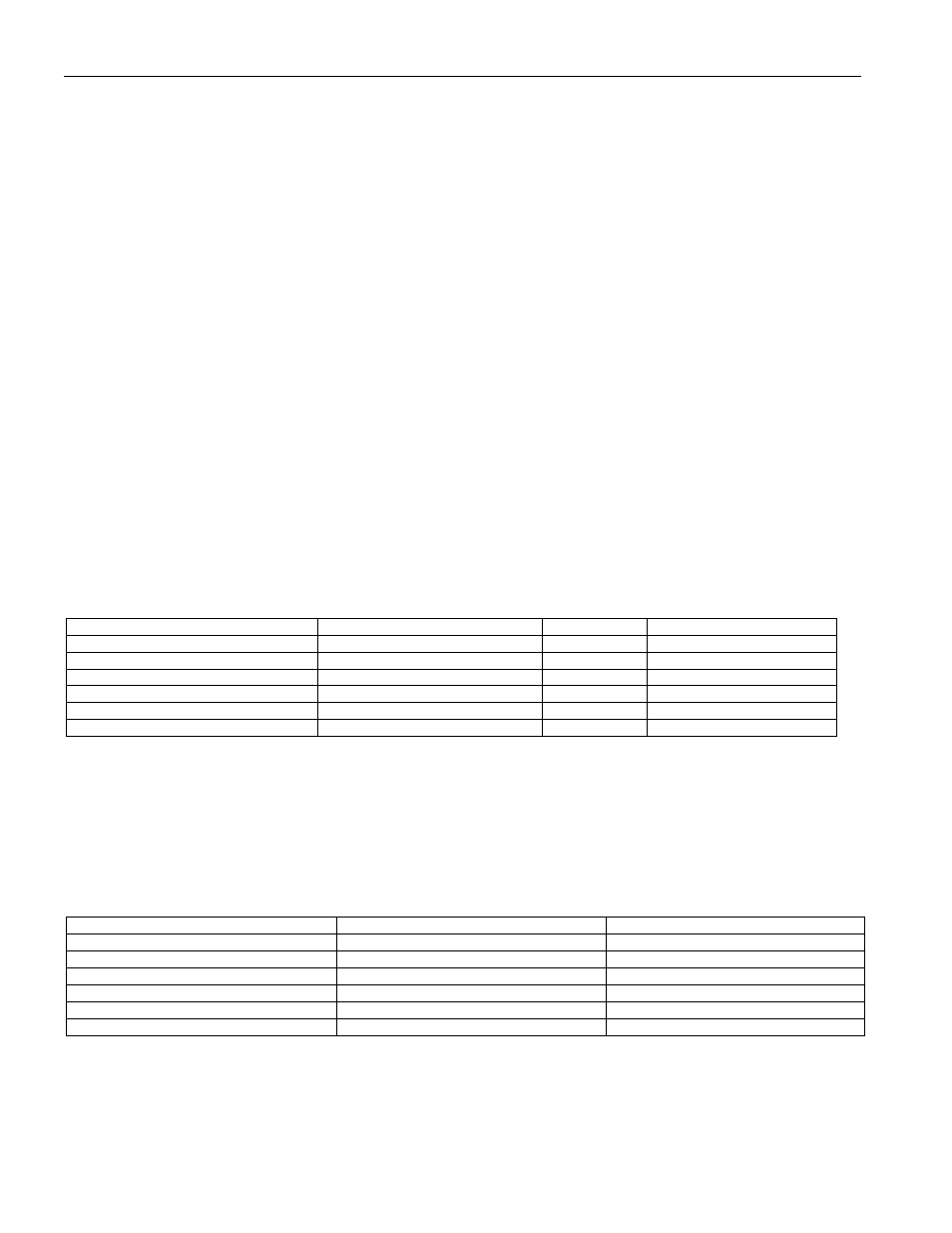
There are six interrupt vector locations in a secure microcontroller. Each interrupt generally has an
enable-control bit, a status flag bit, and a priority bit. Except for the new Power-fail Interrupt, the enable-
control bits are located in the IE register and the priority bits are located in the IP register. The flags are
located in various SFRs. In the case of the Serial Interrupt, there are two sources with the same vector, but
a separate flag indicates the source of the event. Each ISR vector has a unique physical address. For
example, the External interrupt 0 vector is location 0003h, but the Timer 0 vector is 000Bh. Also note, the
flags correspond to the event, not the interrupt. These flags will be activated even if a particular interrupt
is not enabled so that software can poll the event. The flags (except serial port) are cleared when the CPU
calls to the interrupt vector.
INTERRUPT SOURCE
VECTOR ADDRESS
FLAG
FLAG LOCATION
External Interrupt 0
0003h
IE0
TCON.1
Timer Interrupt 0
000Bh
TF0
TCON.5
External Interrupt 1
0013h
IE1
TCON.3
Timer Interrupt 1
001Bh
TF1
TCON.7
Serial I/O
0023h
RI & TI
SCON.0, SCON.1
Power-fail Warning
002Bh
PFW
PCON.5
11.1 Interrupt Sources
As shown above, there are two external interrupts, two timer interrupts, two serial communication
interrupts, and a power-fail interrupt. To use an interrupt (except PFW), the software must globally enable
the interrupt function by setting the EA bit (IE.7). EA is cleared to logic 0 by all resets. Next, each
individual interrupt must be enabled by using the other bits of the interrupt enable (IE) SFR. Each source
has a corresponding bit that must be set to logic 1. These are listed below.
INTERRUPT SOURCE
ENABLE BIT
LOCATION
External Interrupt 0
EX0
IE.0
Timer Interrupt 0
ET0
IE.1
External Interrupt 1
EX1
IE.2
Timer Interrupt 1
ET1
IE.3
Serial Port Interrupt
ES
IE.4
Power-fail Interrupt
EPFW
PCON.3