Maxim Integrated Secure Microcontroller User Manual
Page 42
Secure Microcontroller User’s Guide
42 of 187
DS5001 CRC Register
CRC, 0C1H
D7
D6
D5
D4
D3
D2
D1
D0
RNGE3
RNGE2
RNGE1
RNGE0
—
—
—
CRC
RB-*
RB-*
RB-*
RB-*
RB-*
R = Unrestricted Read Access, B = Modifiable only via Bootstrap Loader, n = Value after Reset, * = Special: see description
CRC.7-4 RNGE3-0
Determines the range over which a power-up CRC will be performed. Addresses
are specified on 4K boundaries. These bits are reset 0 on a no-V
LI
reset and
unchanged by all other resets.
CRC.0 CRC
When set to 1, a CRC check will be performed on power-up or watchdog timeout.
CRC will be checked against stored values. An error will initiate Program Load
mode. These bits are reset 0 on a no-V
LI
reset and unchanged by all other resets.
DS5000 Memory Control Register
MCON, 0C6H
D7
D6
D5
D4
D3
D2
D1
D0
PA3
PA2
PA1
PA0
RA32/8
ECE2
PAA
SL
R*-*
R*-*
R*-*
R*-*
RB-*
RW-*
RT-0
R*-*
R = Unrestricted Read Access, W = Unrestricted Write Access, T = Timed-access Write Only, B = Modifiable only via Bootstrap Loader,
n = Value after Reset, * = Special: see description
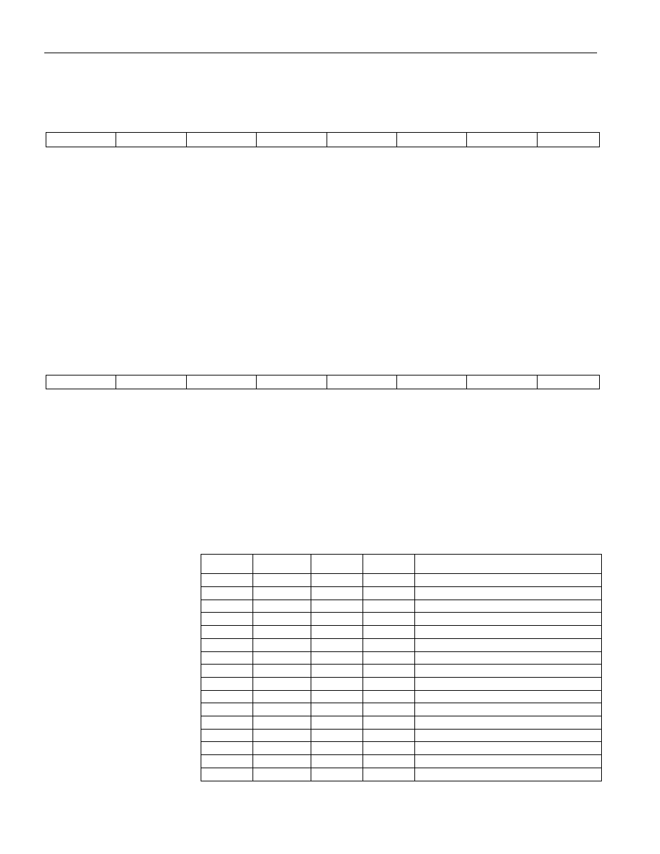
MCON.7-4
PA3–0
Partition Address
Selects the starting address of data memory on the bytewide bus. Program space
lies between address 0000h and the partition address. Writes to these bits are only
allowed when PAA = 1. Timed access is not required to write to PA3-0 once PAA
= 1.These bits are set to 1111b on a no-V
LI
reset or when the security lock bit is
cleared by hardware or the bootstrap loader. They are unchanged by all other
resets. These bits are also reset to 1111b when software attempts to modify them
to 0000b when SL = 1 (illegal condition).
PA3
PA2
PA1
PA0
PARTITION ADDRESS
0
0
0
0
0000h (Invalid when SL = 1)
0
0
0
1
0800h
0
0
1
0
1000h
0
0
1
1
1800h
0
1
0
0
2000h
0
1
0
1
2800h
0
1
1
0
3000h
0
1
1
1
3800h
1
0
0
0
4000h
1
0
0
1
4800h
1
0
1
0
5000h
1
0
1
1
5800h
1
1
0
0
6000h
1
1
0
1
6800h
1
1
1
0
7000h*
1
1
1
1
8000h*