Figure 6-1. power-supply slew rate, Battery-attach procedure – Maxim Integrated Secure Microcontroller User Manual
Page 59
Secure Microcontroller User’s Guide
59 of 187
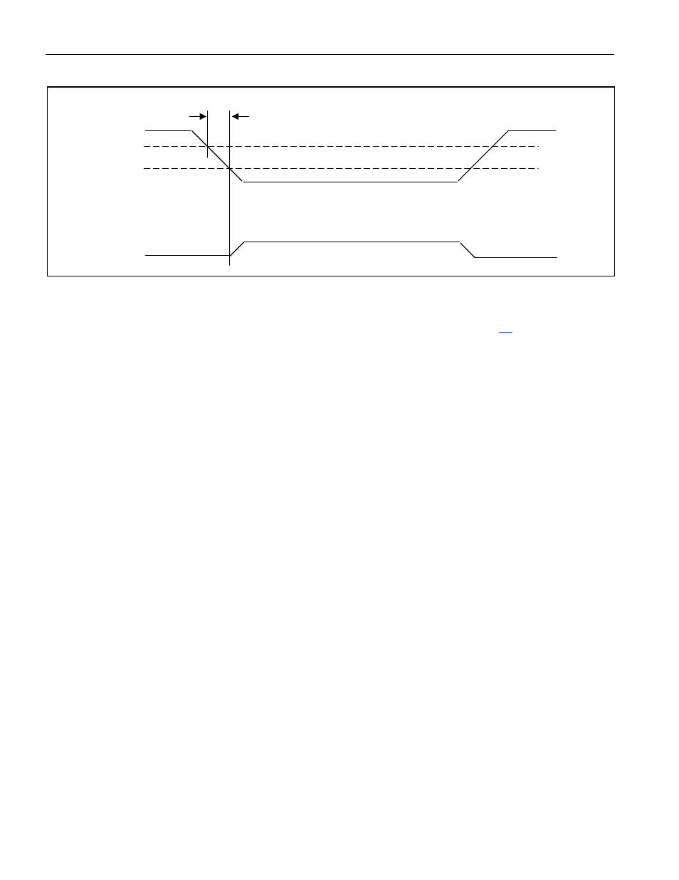
Figure 6-1. Power-Supply Slew Rate
Each time V
CC
is restored, the battery-backed functions remain in their previous state. The exception is
when the device performs a no-V
LI
reset. This special reset event is a one-time, user-initiated action that
forces selected SFR bits to special states. The no-V
LI
reset is documented in Section
, Reset Conditions.
A module user [DS5000(T), DS2250(T), DS2252(T)] never experiences a no-V
LI
reset because it occurs
only once as a part of the factory assembly process.
Battery-Attach Procedure
This section applies to microprocessor chips only, not modules. When a microprocessor is received from
the factory, all nonvolatile functions are absent since there is no backup source connected to the chip. As
mentioned above, the microprocessor must place circuits in a low-power state to prepare for battery
backup. If a battery were attached to an uninitialized chip, the backup current would be unpredictable. For
this reason, the following battery-attach procedure must be followed.
1) Apply V
CC
to the microprocessor.
2) Attach the battery to the V
LI
input.
3) Configure and program the device as normal. (Optional at this time.)
4) Power-down the microprocessor (remove V
CC
) using the guidelines discussed above while leaving the
battery attached.
It is imperative that the battery-attach procedure be followed correctly. Connecting the battery without
performing the battery-attach procedure can result in a high-drain on the battery until V
CC
is first applied,
significantly reducing battery life. Note that the battery-attach procedure does not automatically initiate a
no-V
LI
reset, and battery-backed bits are undefined until initialized by the bootstrap loader, user-software,
or a no-V
LI
reset. Following a battery-attach procedure, the first command sent to the bootstrap loader
must be the Unlock command to initialize the state of the security lock bit.
Important Application Note
Maxim recommends a direct connection between the battery and the V
LI
pin of the microprocessor. The
inclusion of diodes or resistors in series with the V
LI
pin of the microprocessor is not necessary and may
result in a loss of memory integrity under certain circumstances.
In most applications it is not necessary to add decoupling capacitors to the V
CCO
line if a small number of
memory devices will be attached to the pin. If decoupling capacitors are required, the must have a high
40µs, 130µs
V
CC
V
CCMIN
V
LI
LITHIUM
CURRENT