Program status word register psw, 0d0h – Maxim Integrated Secure Microcontroller User Manual
Page 45
Secure Microcontroller User’s Guide
45 of 187
Program Status Word Register
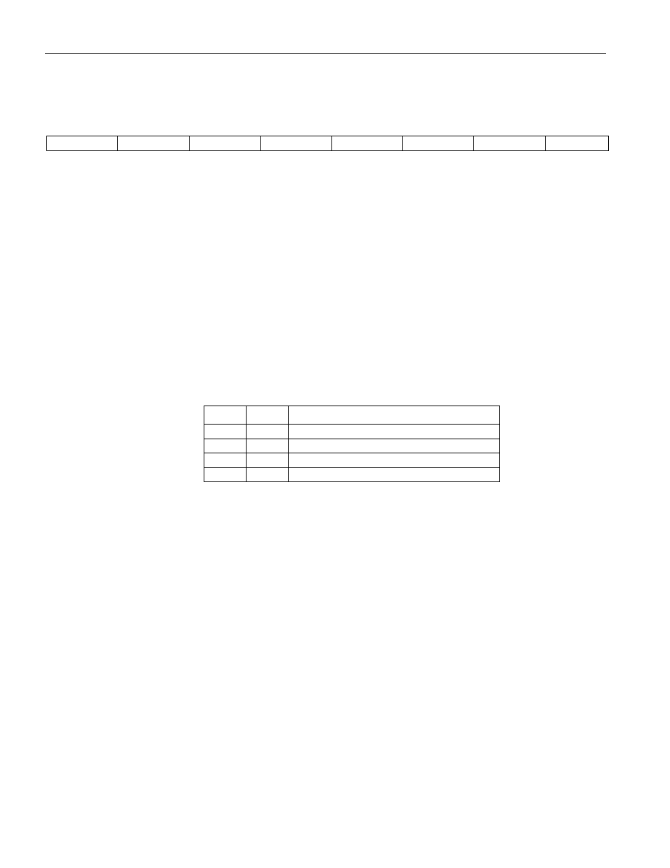
PSW, 0D0H
D7
D6
D5
D4
D3
D2
D1
D0
C
AC
F0
RS1
RS0
OV
P
RW-0
RW-0
RW-0
RW-0
RW-0
RW-0
R-0
R = Unrestricted Read Access, W = Unrestricted Write Access, T = Timed-access Write Only, n = Value after Reset, * = Special: see description
PSW.7
C
Carry
Set when the previous operation resulted in a carry (during addition) or a borrow
(during subtraction). Otherwise cleared.
PSW.6
AC
Auxiliary-Carry
Set when the previous operation resulted in a carry (during addition) or a borrow
(during subtraction) from the low-order nibble. Otherwise cleared.
PSW.5
F0
User Flag 0
General-purpose flag bit that can be set or cleared as needed.
PSW.4-3
R1–R0
Register Bank Select
Used to select an 8-byte bank of registers within the data register space to be
assigned as R0–R8 in subsequent instructions. The 8-byte bank starting address
selection is as follows:
R1
R0
DATA REGISTER ADDRESS (R0)
0
0
00h
0
1
08h
1
0
10h
1
1
18h
PSW.2
OV
Overflow
Set when a carry was generated into the high-order bit, but not a carry out of the
high-order bit as a result of the previous operation, and vice versa. OV is normally
used in 2’s complement arithmetic.
PSW.0
P
Parity
Set if the modulo-2 sum of the eight bits of the accumulator is 1 (odd parity);
cleared on even parity.