1 power-on reset, Power-on reset, Figure 10-1. power-on reset timing – Maxim Integrated Secure Microcontroller User Manual
Page 87
Secure Microcontroller User’s Guide
87 of 187
10.1.1 Power-On Reset
The secure microcontroller family provides an internal power-on reset capability that requires no external
components. When voltage is applied to the V
CC
pin from a power-off condition, the device automatically
performs an internal reset sequence to prepare the processor for execution of the application software.
The traditional capacitor reset circuit should not be used.
illustrates the timing associated
with the power-on reset cycle.
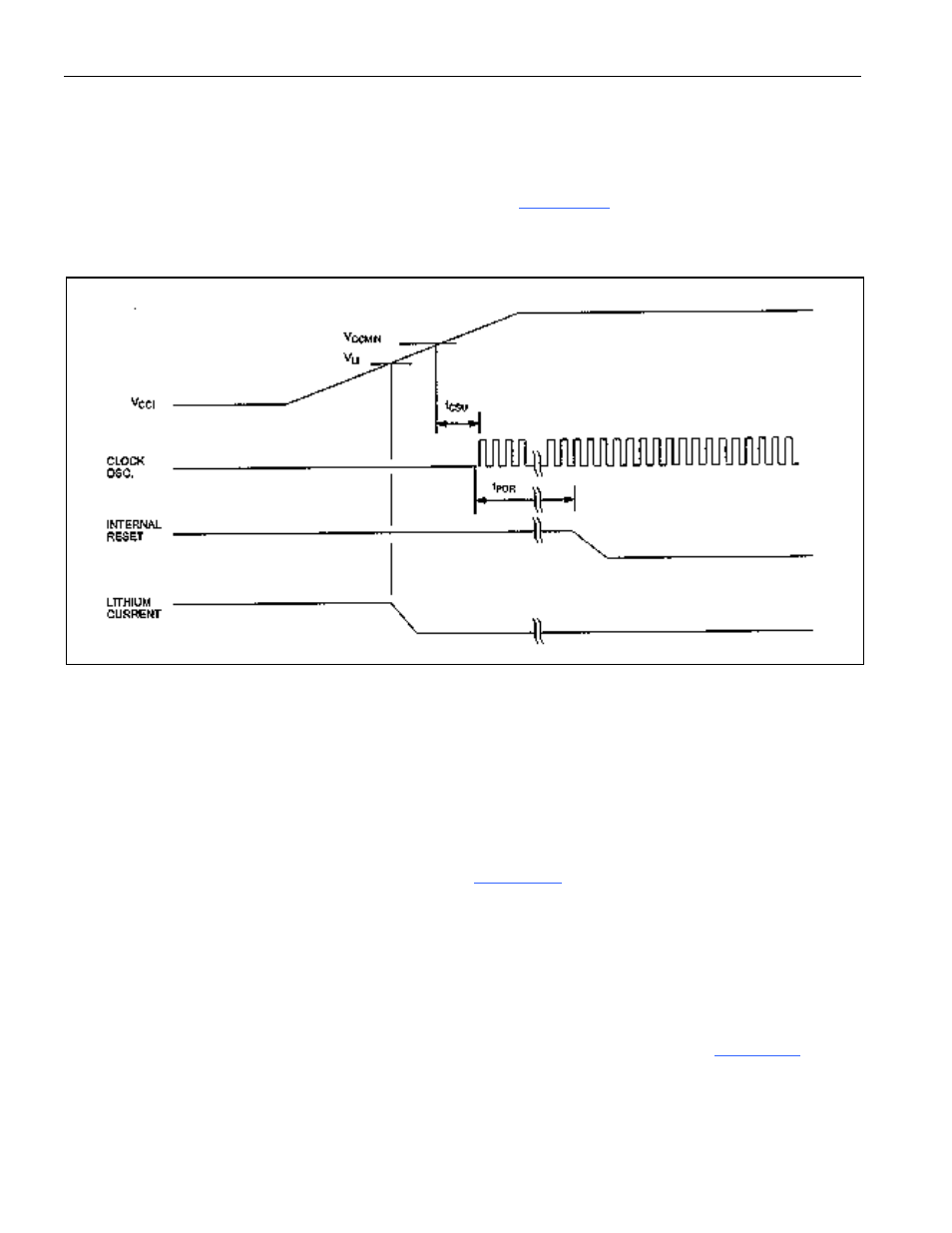
Figure 10-1. Power-On Reset Timing
This cycle begins with power-on reset delay time. This is generated by the internal control circuitry to
allow the internal clock oscillator to start up from its halted state that is in effect when V
CC
is below
V
CCMIN
. The period t
CSU
is a mechanical startup time that is dependent on the individual crystal. The delay
shown as t
POR
in the figure is generated by internal circuitry that counts a total of 21,504 (1.792ms at
12MHz) clock oscillator periods before it allows the internal reset line to be released. The purpose of this
delay is to allow time for the clock frequency to stabilize.
The power-on reset delay is not the total amount of time that must pass before execution can begin in the
application from the initial application of V
CC
voltage. First the power supply slew rate is required for
V
CC
to rise from 0V to the V
CCMIN
threshold shown in
. Next, operation with a crystal is partly
mechanical and some time is required to get the mass of the crystal into vibrational motion. The user
should consult the crystal vendor for a start-up time specification.
When a power-on reset cycle is in progress, the external RST pin has no effect on internal operation.
Once control of the processor is transferred to the user’s program, a hardware reset may be issued
externally via the RST pin.
A power-on reset causes special initialization to be performed on the SFR as shown in