Serial control register scon, 098h – Maxim Integrated Secure Microcontroller User Manual
Page 39
Secure Microcontroller User’s Guide
39 of 187
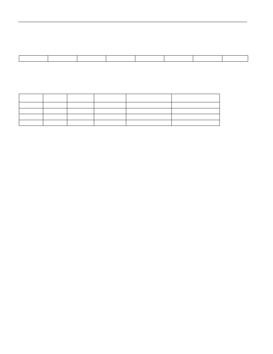
Serial Control Register
SCON, 098H
D7
D6
D5
D4
D3
D2
D1
D0
SM0
SM1
SM2
REN
TB8
RB8
TI
RI
RW-0
RW-0
RW-0
RW-0
RW-0
RW-0
RW-0
RW-0
R = Unrestricted Read Access, W = Unrestricted Write Access, T = Timed-access Write Only, n = Value after Reset, * = Special: see description
SCON.7, SCON.6:
SM0, SM1
“Mode Select”:
Used to select the operational mode of the serial I/O port as follows:
SM0
SM1
MODE
FUNCTION
LENGTH (BITS)
CLOCK PERIOD
0
0
0
SYNC
8
12 t
CLK
0
1
1
ASYNC
10
Timer 1 Overflow
1
0
2
ASYNC
11
64 t
CLK
or 32 t
CLK
1
1
3
ASYNC
11
Timer 1 Overflow
SCON.5
SM2
Multiple MCU Comm
Used to enable the multiple microcontroller communications feature for modes 2
and 3. When SM2 = 1, RI IS activated only when serial words are received which
cause RB8 to be set to 1.
SCON.4
REN
Receive Enable
When set to 1, the receive shift register is enabled. Disabled when cleared to 0.
SCON.3
TB8
Transmitted Bit 8
Can be set or cleared to define the state of the 9th data bit in modes 2 and 3 of a
serial data word.
SCON.2
RB8
Received Bit 8
Indicates the state of the 9th data bit received while in modes 2 or 3. If mode 1 is
selected with SM2 = 0, RB8 is the state of the stop bit which was received. RB8 is
not used in mode 0.
SCON.1
TI
Transmit Interrupt
Status bit used to signal that a data word has been completely shifted out. In mode
0, it is set at the end of the 8th data bit. Set when the stop bit is transmitted in all
other modes.
SCON.0
RI
Receive Interrupt
Status bit used to signal that a serial data word has been received and loaded into
the receive buffer register. In mode 0, it is set at the end of the 8th bit time. It is set
at the midbit time of the incoming stop bit in all other modes of a valid received
word according to the state of SM2.