Figure 5-2. ds5000 series module block diagram, Figure 5-2 – Maxim Integrated Secure Microcontroller User Manual
Page 52
Secure Microcontroller User’s Guide
52 of 187
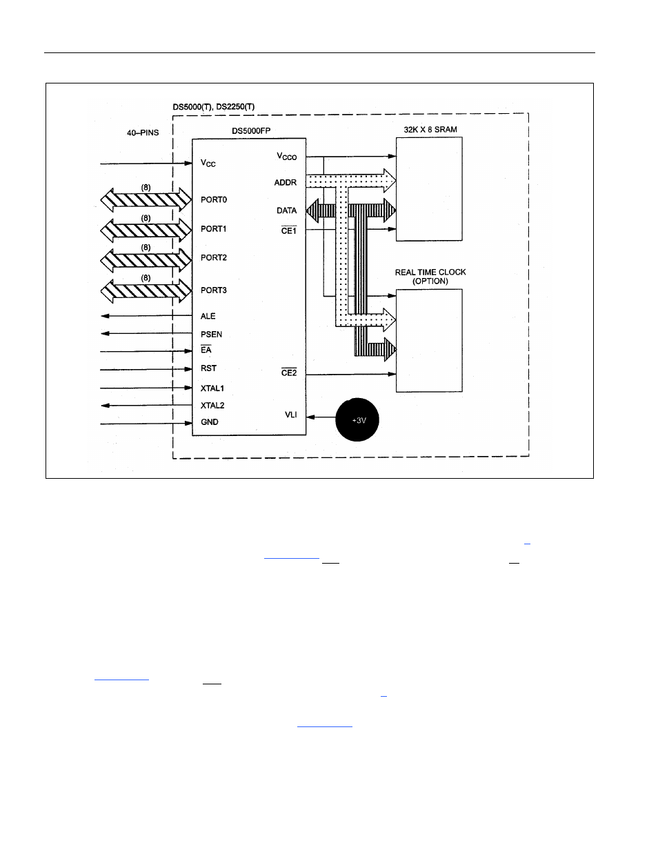
Figure 5-2. DS5000 Series Module Block Diagram
The DS5001FP/DS5002FP has several memory options. It can be connected to between one 8kB SRAM
and four 32kB SRAMs. It also supports one 128kB SRAM. In most cases the DS5001FP is used for its
greater memory access so it is not used with 8kB RAMs. In the partitionable mode (Section
), the device
can be connected to one or two SRAMs.
illustrates the connection of two 32kB x 8 SRAMs.
Each RAM has its own chip enable, with a common
WE
generated by the DS5001FP R/
W
signal. When
using the DS5001FP/DS5002FP with only one RAM, the second chip enable simply remains
unconnected. This solution provides 64kB of memory the user can partition into program and data
segments. The partition setting has no affect on the interconnect. Using the partition, the microcontroller
determines which memory blocks are program and write protects the appropriate addresses.
In the nonpartitionable case, the DS5001FP/DS5002FP can be connected to three or four 32kB x 8
SRAMs.
shows the four RAM case. Each RAM has its own chip enable. To use three RAMs,
omit the unused chip enable (
CE2
. This hardware configuration is similar
to the partitionable mode previously discussed. While this provides all 128kB of memory, it requires
more space and cost than the version shown in
. This uses the 128kB SRAM, which contains
all program and data memory. Note the MSEL signal is connected to ground to initiate this mode. The
user must still configure the PM bit and range during program loading.