Real-time clock (rtc), 1 ds5000t/ds2250t rtc, Ds5000t/ds2250t – Maxim Integrated Secure Microcontroller User Manual
Page 155
Secure Microcontroller User’s Guide
155 of 187
17. REAL-TIME CLOCK (RTC)
Many user applications require a time-of-day clock. For this reason, all secure microcontroller modules
have RTC options. These include the DS5000T DIP and the DS2250T, DS2251T, and DS2252T SIMMs.
There are two types of RTCs used in Maxim modules, which are described below.
17.1 DS5000T/DS2250T RTC
The RTC used on the DS5000T and DS2250T provide permanently powered time-of-day monitoring in a
convenient BCD format. The clock runs from an internal 32kHz crystal and is generally independent of
the microcontroller. It provides time of day information including 0.01 second, seconds, minutes, hours,
day, date, month and year to two minutes per month accuracy. It does not provide any interrupt
capability, although this feature is in the DS2251T and DS2252T modules.
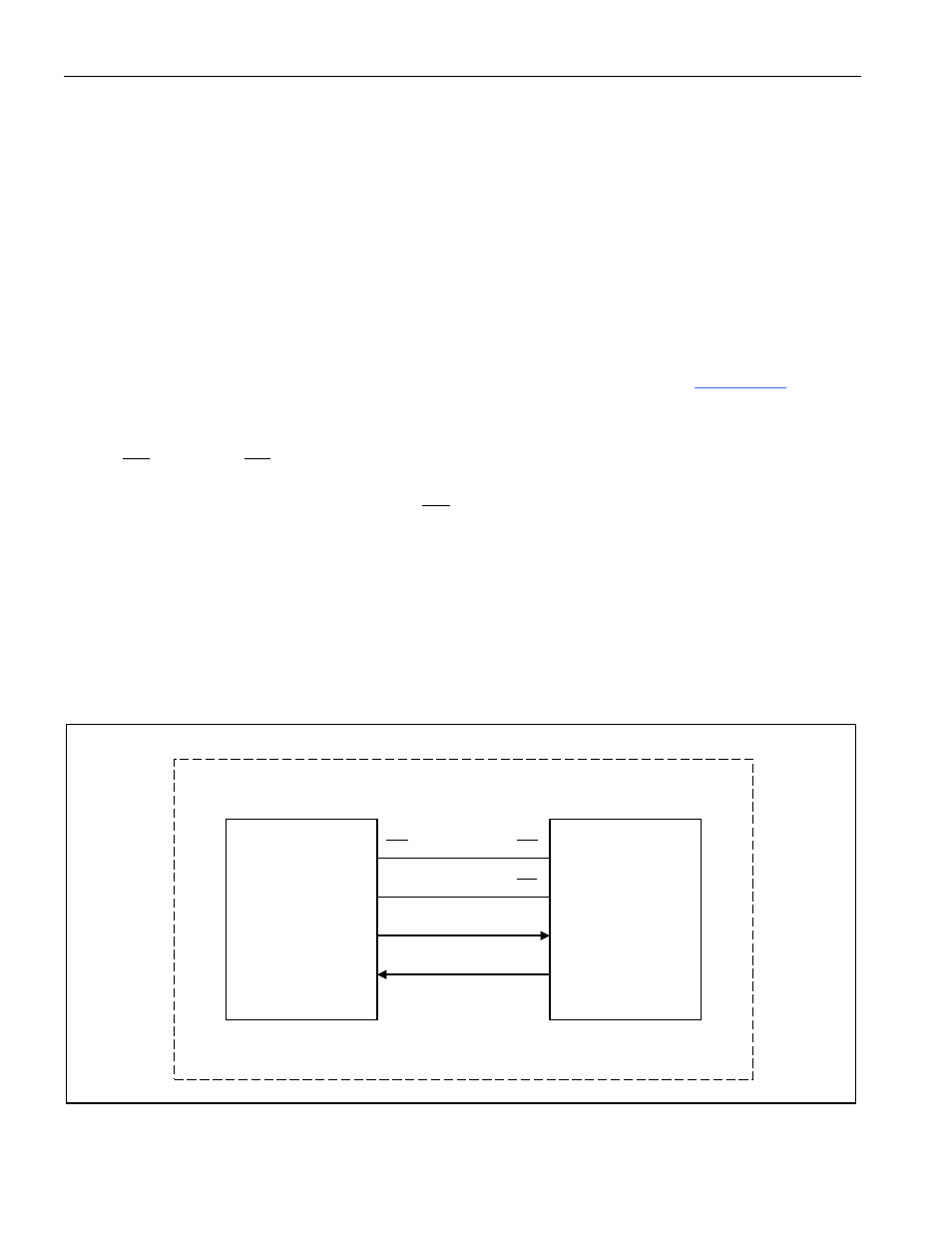
The RTC used in the DS5000T/DS2250T is transparent to the memory map.
functional block diagram of the interconnection between the DS5000FP and RTC used on the
DS5000T/DS2250T. It is fundamentally a serial device that resides on the address bus. To access the
clock, the user must set the ECE2 bit at MCON.2 to a logic 1. This will cause all MOVX instructions to
access
CE2
instead of
CE1
. Once ECE2 is set, the bytewide Address bit 2 serves as a write enable and
Address bit 0 serves as the data input. Bit 7 of the bytewide Data bus serves as the data output. Notice
that the read/write line is not used. For each
CE2
access, the RTC will watch the value of A0 on the
bytewide bus for a particular 64-bit security pattern. This pattern checking prevents accidentally invoking
the clock. Since these must be write operations, A2 must be a logic 0 for each write. The clock will take
no action unless the 64 pattern bits are written in the correct order. Any error causes the pattern
comparator to start over. Thus the users must “really” intend to communicate with the RTC. Once the
security pattern is written, the next 64 bits are time of day and calendar functions. Thus 128 read/writes
are required for any time of day access. Data is written using BA0 and read using BD7. Thus the address
actually writes data, but data is read normally using one bit.
Figure 17-1. DS5000T/DS2250T Functional Block Diagram
CE2
BA2
BA0
BD7
Q
D
CE1
WE
DS5000
CPU
RTC
DS5000T OR DS2250T