Toshiba, 5л cables, 2 external device connections and grounding – Toshiba LF434 User Manual
Page 28
Attention! The text in this document has been recognized automatically. To view the original document, you can use the "Original mode".
TOSHIBA
6 . F . 8 A 0 7 7 0
5Л Cables
Use the kind of ciibles shown in Tahle
lo
wire the converler.
Table 5.1 Cables
Name
Cable type
Nominal
cross-.sectional
area
Overall diameter
Power cable
Three-wire sheathed
cable (Note)
2
mm^
11 to 13 mm
1/0 cable
I'he number of wires for the output cable depends on Ihc
system spccificiirions. Use a shielded cable with nominal
cross-scctional area of 1.25 inrii^ and overall diameter of
n to 13 mm.
Notei Use a four-wire cable if the arresters are to be used. See Figure 5.1 below,
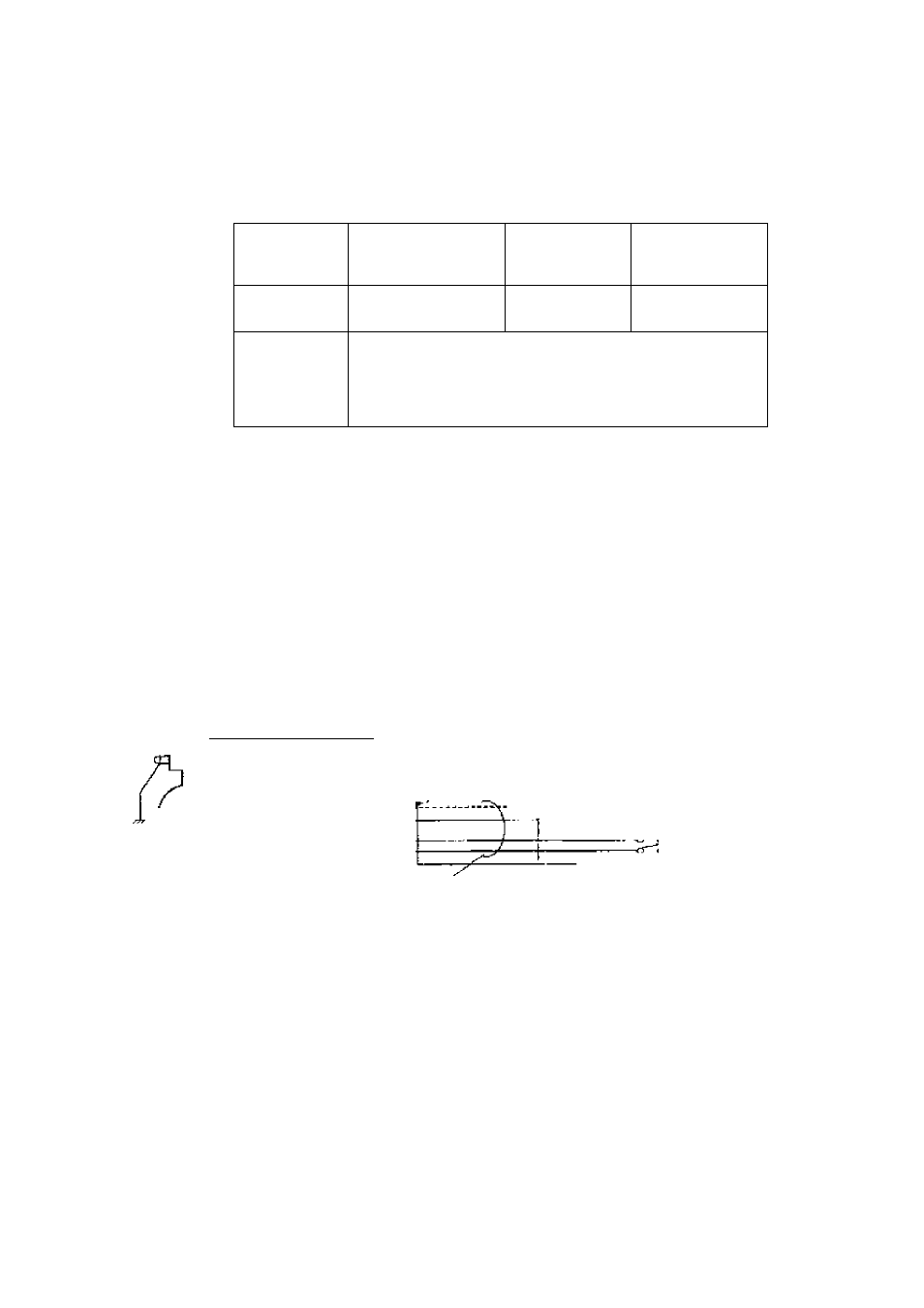
5.2 External Device Connections and Grounding
The terminal board connections of the LF434/LF404 flowmeter arc shown in Figure 5.1.
Proceed with wiring as described in Section 5.4, '‘Wiring Procedure.”
If power supply is specified as DC, use M as positive (+) and 1.2 as negative (-) terminals.
Instrument Panel:
ordered separately
Plown-fceler
[C1 |~1^Т
рс
|51
с
|[
с
О
ы
[ ni|oQ^noi| -
IV wire
5.5тзп"
or more
■; Cument output (4—20 mA dc
)
- Digital Output I
; ■; r>igilai
2
:
Digjiit! Input (20 to 30 V de)
*1
Cixrourided with 1 (X)Q or less
1/0 cable
R>wer cable
’ ■ \
.......... ! ground resistance.
— > Power Supply
It “"2
^
Power Switch
*^1 To use the arresters, ground the ON 13 terminal using the wire shown in broken line.
*2 Locate an external double-pole power switch on the power line near the flowmeter and within easy
operation. Mark one the switch as the tlisconnecting device for the flow^meler.
Use an appropriate switch of the rating shown below:
Recommended sw'itch rating; Rating
25D V ac, 6A or more
Inrush current 15 Лог more
Figci re 5.1 Term in a t В lock Connection s
-
2 7
-