U j cautionary notes on communications, Interference on 4-2qma current signal, Toshiba – Toshiba LF434 User Manual
Page 133
Attention! The text in this document has been recognized automatically. To view the original document, you can use the "Original mode".
TOSHIBA
6F8A0 7 7.0
U J Cautionary Notes on Communications
Observe the following notes and limit at Jo ns when you use the coifiTnunicaiioRS function.
■ C u rrent out |j ut ] oad
Load resistance: 240 to L kU (including communicutions line resistance)
Load capacitance: 0.22/«F maxiinum (including communications line capachaace)
Load inductance: 4mTT maximum (iiicJuduig communications line inductance)
Cahic
length:
2 km inaximuin (approximate value when
[ . 2 5
mm'shielded cable
is used under i^tandarJ operating conditions.)
■ Wiring cable
Use a shielded output cable as specified in Table 5T.
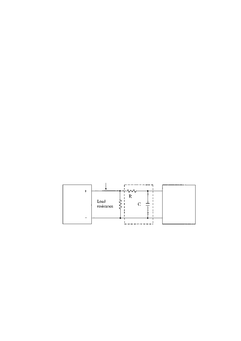
■ Interference on 4-2QmA current signal
To communicate with the flowmeter^ a digital signal (amplitude 0,4 to 0.8 V in the case of
500 Q load resistance) wdth a frequency of 1,2 to 2,2 kHz is superimposed on the 4-20mA
current signal. If
a
high-response receiving instrument is connected to the current output line,
!he superimposed communications signal may interfere with the Instrument, To preveni this
interference, put a low'-pass filter with a time constant of about 100 ms into the input circuit of
the receiving instrument.
Current output
Converter
Filter
Receiving inslrumem
Figure 11.3 Filter connection example
- 132 -