2 batch operations – Rice Lake 880 Performance Series Indicator/Controller Technical/Service Manual User Manual
Page 89
Setpoints
83
8.2
Batch Operations
Batches are controlled by digital inputs or EDP commands.
Batch Run
(BATRUN digital input) If a BATRUN digital input is configured, it must be active (low) for a batch to
be started, and for it to continue to run. If a batch is running and the input becomes inactive (high), it
will stop the batch at the current batch setpoint and turn off all associated digital outputs.
Batch Start
(BATSTR digital input or BATSTR EDP command) If the BATRUN digital input is active (low), or is
not assigned, batch start will start a batch, resume a paused batch or resume a stopped batch. If the
BATRUN digital input is inactive (high), batch start will reset the current batch.
Batch Pause
(BATPAS digital input or BATPAUSE EDP command) The BATPAS digital input will pause an
active batch, turning off all associated digital outputs EXCEPT those associated with CONCUR
and TIMER setpoints, while the input is active (low). As soon as the BATPAS digital input is made
inactive (high), the batch will resume.
BATPAUSE EDP command works the same, except the batch will not resume until a batch start
signal is received.
Batch Stop
(BATSTP digital input or BATSTOP EDP command) Stops an active batch at the current setpoint and
turns off all associated digital outputs.
Batch Reset
(BATRST digital input or BATRESET EDP command) Stops and resets an active batch to the
beginning of the process.
WARNING
To prevent personal injury and equipment damage, software-based interrupts must always be supplemented
by emergency stop switches and other safety devices necessary for the application.
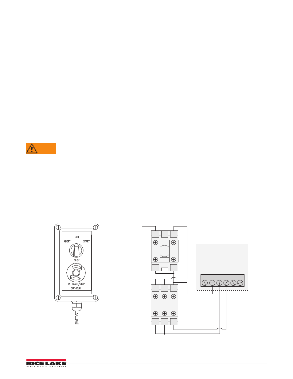
Batching Switch
The batching switch option, PN 19369, comes as a complete unit in an FRP enclosure, with legend plate, locking
stop switch (mushroom button), and a run/start/abort 3-way switch.
Both switches are wired into the indicator’s digital I/O terminal strip as shown in Figure 8-1. Each switch uses a
separate digital input. Digital input #1 must be set to
BATSTR
and #2 must be set to
BATRUN
.
Once cables and switches have been connected to the indicator, use the setup switch to place the indicator in setup
mode. Use the DIG I/O menu (see Section 3.2.14 on page 54) to configure digital input and output functions.
RED
WHITE
BLACK
RED
BLACK
STOP/START MUSHROOM SWITCH
ABORT/RUN/START SWITCH
A
B
O
R
T
S
T
A
R
T
3
4
1
2
NO
NC
NC
NO
NO
+5VDC
GND
DIO1
DIO2
DIO3
DIO4
DIGITAL I/O
1
2
4
5
6
3
CPU BOARD
3
4
1
2
3
4
Figure 8-1. Batching Switch and Wiring Diagram Example