4 display board replacement, 5 cable connections, 1 load cells – Rice Lake 880 Performance Series Indicator/Controller Technical/Service Manual User Manual
Page 22: 4 display board replacement 2.5 cable connections, Load cells
16
880 Technical/Service Manual
2.4
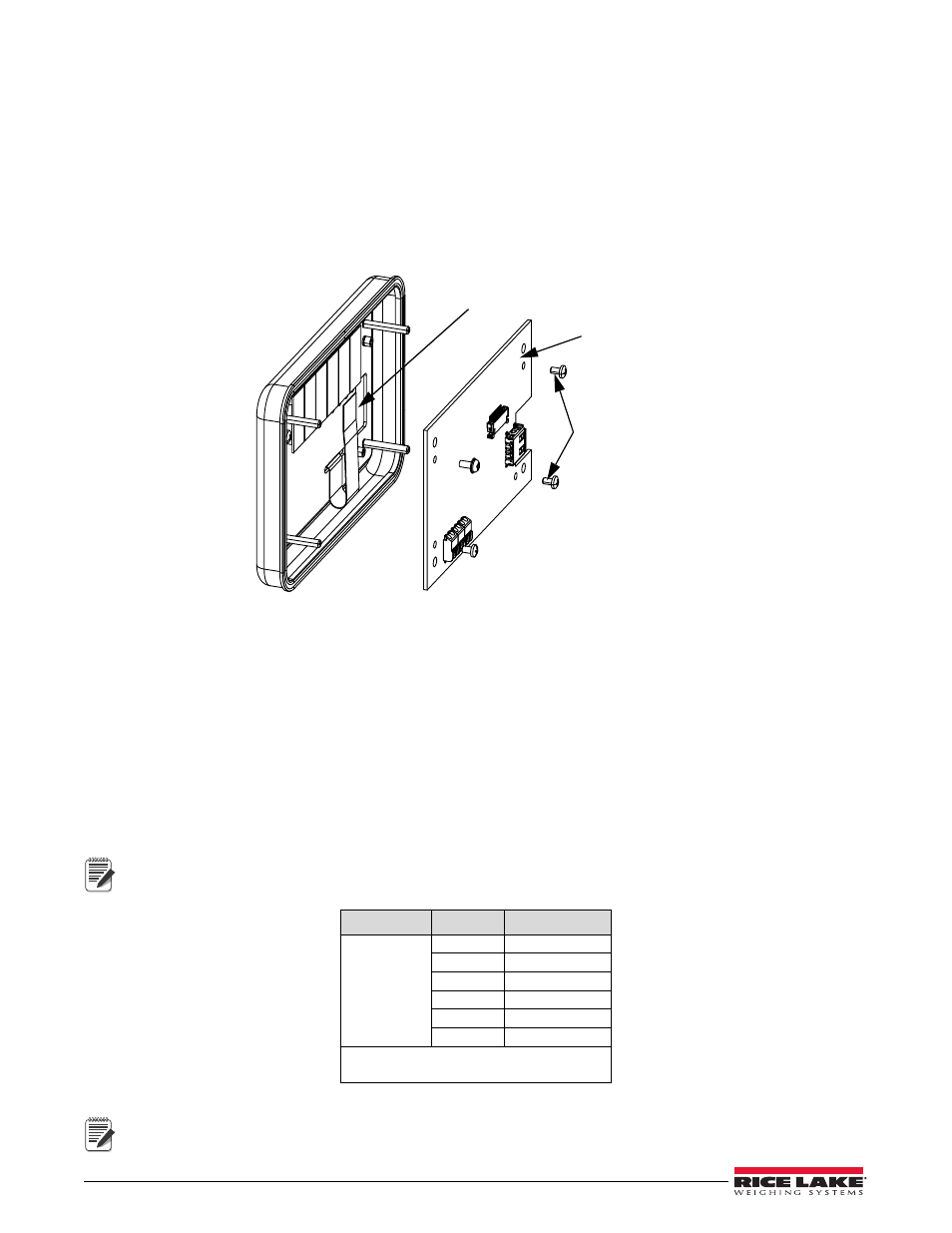
Display Board Replacement
If the 880 display board must removed, use the following procedure:
1. Disconnect power to the unit.
2. Remove controller assembly (see Section 2.3).
3. Disconnect cable assembly.
4. To remove the display assembly, loosen and remove four Kep nuts securing the DIN rail and display
assembly to the panel (see Figure 2-3).
5. Remove four screws and pull display board from the display assembly.
Display Board
Screws
Cable Assembly
Figure 2-9. VFD Board
6. To replace the display board, reverse the above procedure.
2.5
Cable Connections
The 880 has six external connectors, a terminal connector for the power cord, and a cutout for installed options.
Enclosure disassembly is not required to make connections to load cells, communications, digital inputs, and
digital outputs. These connectors are all externally mounted on the back of the controller.
2.5.1
Load Cells
To attach cable from a load cell or junction box, route the cable to the external J1 connector. Wire the load cell
cable from the load cell or junction box to connector J1 as shown in Table 2-2. If using 6-wire load cell cable (with
sense wires), open the unit (see Section 2.2) and remove jumpers JP5 and JP6.
Table 2-2. J1 Pin Assignments
Connector
Pin
Function
J1
1
+SIG
2
–SIG
3
+SENSE
4
–SENSE
5
+EXC
6
–EXC
For 6-wire load cell connections, remove
jumpers JP5 and JP6.
Note
Note
For 4-wire installation, leave jumpers JP5 and JP6 on (see Figure 2-12).
Shield wire will attach to ground clamp on backplate.