0 installation, 1 unpacking and assembly, 1 parts kit components – Rice Lake 880 Performance Series Indicator/Controller Technical/Service Manual User Manual
Page 16: Installation, Parts kit components
10
880 Technical/Service Manual
2.0
Installation
This section describes procedures for connecting load cells, digital I/O, and serial communications cables to the
880 indicator. Instructions for replacement of the circuit boards are included, along with assembly drawings and
parts lists for the service technician.
CAUTION
• Use a wrist strap to ground yourself and protect components from electrostatic discharge (ESD) when working inside
the indicator enclosure.
• Procedures requiring work inside the indicator must be performed by qualified service personnel only.
• The supply cord serves as the power disconnect for the
880
. The power outlet supplying the indicator must be installed
near the unit and be easily accessible.
2.1
Unpacking and Assembly
Immediately after unpacking, visually inspect the 880 to ensure all components are included and undamaged. The
shipping carton should contain the controller, display, Operator's Manual, CD and parts kit.
If any parts were
damaged in shipment, notify Rice Lake Weighing Systems and the shipper immediately.
2.1.1
Parts Kit Components
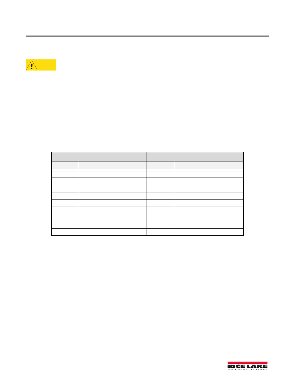
The following items are found in the parts kit:
Table 2-1. Parts Kit
Parts Kit, AC Power (PN 152235)
Parts Kit, DC Power (PN 153647)
Part No
Description
Part No
Description
14621
Nut, Kep 6-32NC Hex
14621
Nut, Kep 6-32NC Hex
15130
Washer, Lock No 6 Type A
15130
Washer, Lock No 6 Type A
152334
Conn, 3 Pos Screw Terminal
15888
Terminal Block, 3 position
153873
Conn, 3 Pos Screw Terminal
153873
Conn, 3 Pos Screw Terminal
153883
Conn,6 Pos Screw Terminal
153883
Conn,6 Pos Screw Terminal
157074
Ferrite,EMI/RFI Clamp-on
157074
Ferrite,EMI/RFI Clamp-on
53075
Clamp,Ground Cable Shield
53075
Clamp,Ground Cable Shield
67550
Clamp,Ground Cable Shield
67550
Clamp,Ground Cable Shield
94422
Label,Capacity .40 x 5.00
94422
Label,Capacity .40 x 5.00