Rockwell Automation Liqui-Flo V2.0 AC Drive User Manual
Page 96
96
Rockwell Automation Publication D2-3518-3 - May 2013
Chapter 9
Sets the response time of slip compensation.
Parameters in the Slip Comp Group (121...123) are used to enable and tune the
slip compensation regulator. To allow the slip compensation regulator to control
drive operation, Speed Mode (80) must be set to 1 (Slip Comp).
Displays the present amount of adjustment being applied as slip compensation.
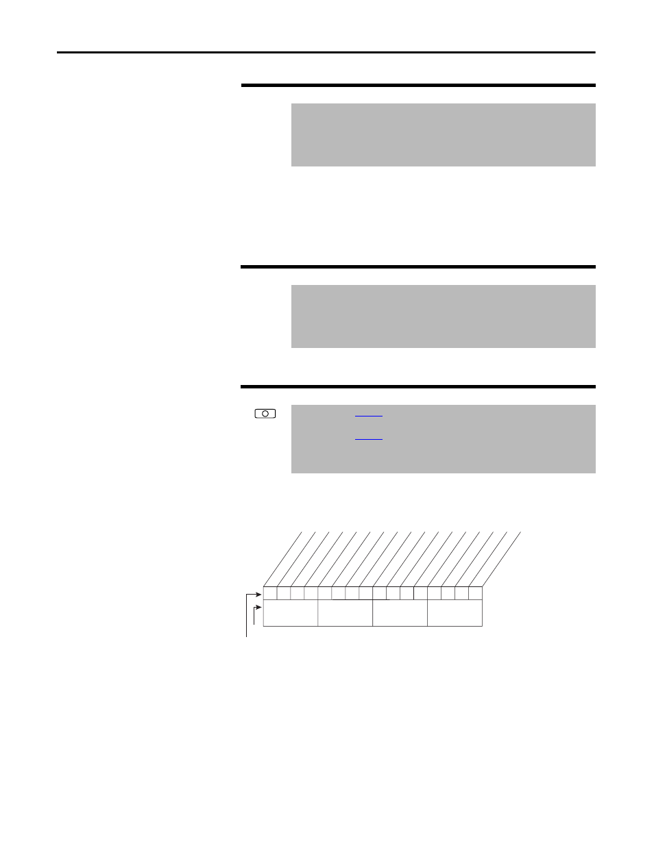
Selects specific features of the PI regulator.
Figure 40 - PI Configuration (124)
Bit 0 – Excl Mode (Exclusive Mode)
•
Enabled = Selects speed regulation.
•
Disabled = Selects trim regulation.
Bit 1 – Invert Error
•
Enables/disables the option to invert the sign of the PI error signal.
Enabling this feature creates a decrease in output for an increasing error
and an increase in output for a decreasing error.
122
Slip Comp Gain
Range:
1.0...100.0 [0.1]
Default:
40.0
Access:
1
Path: Speed Command > Slip Comp
See also:
80, 121, 122
123
Slip RPM Meter
Range:
-/+300.0 RPM
Default:
Read Only
Access:
1
Path: Speed Command > Slip Comp
See also:
80, 121, 122
124
PI Configuration
Range:
See
Default:
See
Access:
1
Path: Speed Command > Process PI
See also:
125...138
0
0
0
0
0
0
0
0
x
x
x
x
x
x
x
x
0
0
1
1
2
3
4
5
6
7
8
9
11
12
13
14
15
1 =Enabled
0 =Disabled
x =Reserved
Bit #
Factory Default Bit Values
Excl Mode
In
ve
rt Error
Preload Mode
Ramp Ref
Zero Clamp
Fe
edbak Sqr
t
Stop Mode
Anti-Windup
Nibble 1
Nibble 2
Nibble 3
Nibble 4