Determining drive status using the status leds – Rockwell Automation Liqui-Flo V2.0 AC Drive User Manual
Page 196
196
Rockwell Automation Publication D2-3518-3 - May 2013
Chapter 10
5.
Measure the DC bus potential with a voltmeter while standing on a
non-conductive surface and wearing insulated gloves. See
for Frame 4.
6.
Once the drive has been serviced, reattach the power module cover and
close the enclosure door.
7.
Turn on the circuit breaker.
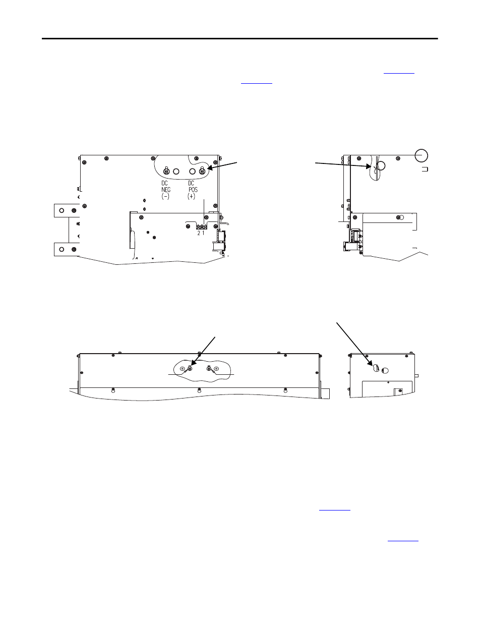
Figure 77 - Location of DC Bus Measuring Points (Frame 3)
Figure 78 - Location of DC Bus Measuring Points (Frame 4)
Determining Drive Status
Using the Status LEDs
The inverter and rectifier sections each have a status LED.
For Frame 3 drives, the status LEDs are located on the Communication Interface
board, and are labeled on the board itself as INV STATUS (inverter) and
ACTIVE RECT. STATUS
(rectifier). See
For Frame 4 drives, the status LEDs are located on the Control Board, and are
labeled on the board itself as B2 (inverter) and B1 (rectifier). See
.
DC Bus measurement points on
laminated bus assembly.
0.25 in. x .032 in. male faston.
Accessible by removal of top cover.
Front View of Frame 3 Power Module
Right Side View of
Frame 3 Power Module
DC
POS.
(+)
DC
NEG.
(-)
Front View of Frame 4 Power Module
Right Side View of
Frame 4 Power Module
DC Bus measurement points on laminated bus assembly.
0.25 in. x .032 in. male faston.
Accessible by removal of top cover.