Figure 65 – Rockwell Automation Liqui-Flo V2.0 AC Drive User Manual
Page 142
142
Rockwell Automation Publication D2-3518-3 - May 2013
Chapter 9
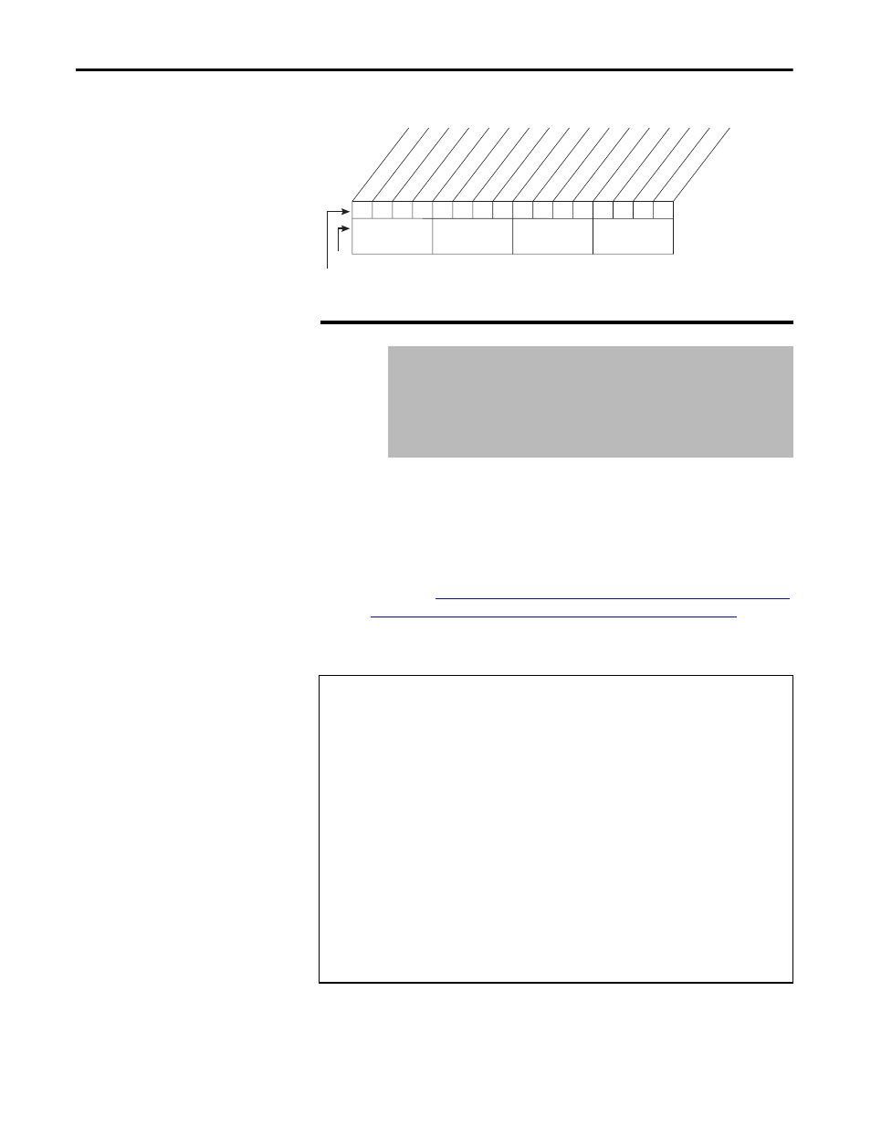
Figure 65 - Anlg in Sqr Root (321)
The drive scales the value read from the user-configurable analog input and
converts it to units usable for the application. You control the scaling by setting
parameters that associate a low and high point in the input range with a low and
high point in the target range.
Analog In 1 Hi sets the highest input value to the user-configurable analog input
1 scaling block. See
AC Line I/O Board Description (Frame 3 Only) on page 25
through
Combined I/O Board Description (Frame 4 Only) on page 29
for a
description of I/O hardware that is present on this drive and is controlled by the
inverter.
322
Analog In 1 Hi
Range:
4.000...20.000 mA [0.001 mA]
-/+10.000V [0.1V]
0.0...10.000V [0.1V]
Default:
20.000 mA
Access:
0
Path: Inputs & Outputs > Analog Inputs
See also:
91, 92, 320
Analog Input Scaling Example
Assume:
Speed Ref A Sel = Analog In 1
Minimum Freq = 0 Hz
Maximum Freq = 60 Hz
Analog In 1 Lo = 0.0V
Analog In 1 Hi = 10.0V
This is the default setting, where minimum input (0V) represents Minimum
Speed and maximum input (10V) represents Maximum Speed.
x
x
x
x
x
x
x
x
x
x
x
x
x
x
0
0
0
0
1
1
2
3
4
5
6
7
8
9
11
12
13
14
15
1 =Enable
0 =Disable
x =Reserved
Bit #
Factory Default Bit Values
Analog ln 1
Analog ln 2
Nibble 1
Nibble 2
Nibble 3
Nibble 4