Rockwell Automation Liqui-Flo V2.0 AC Drive User Manual
Page 76
76
Rockwell Automation Publication D2-3518-3 - May 2013
Chapter 9
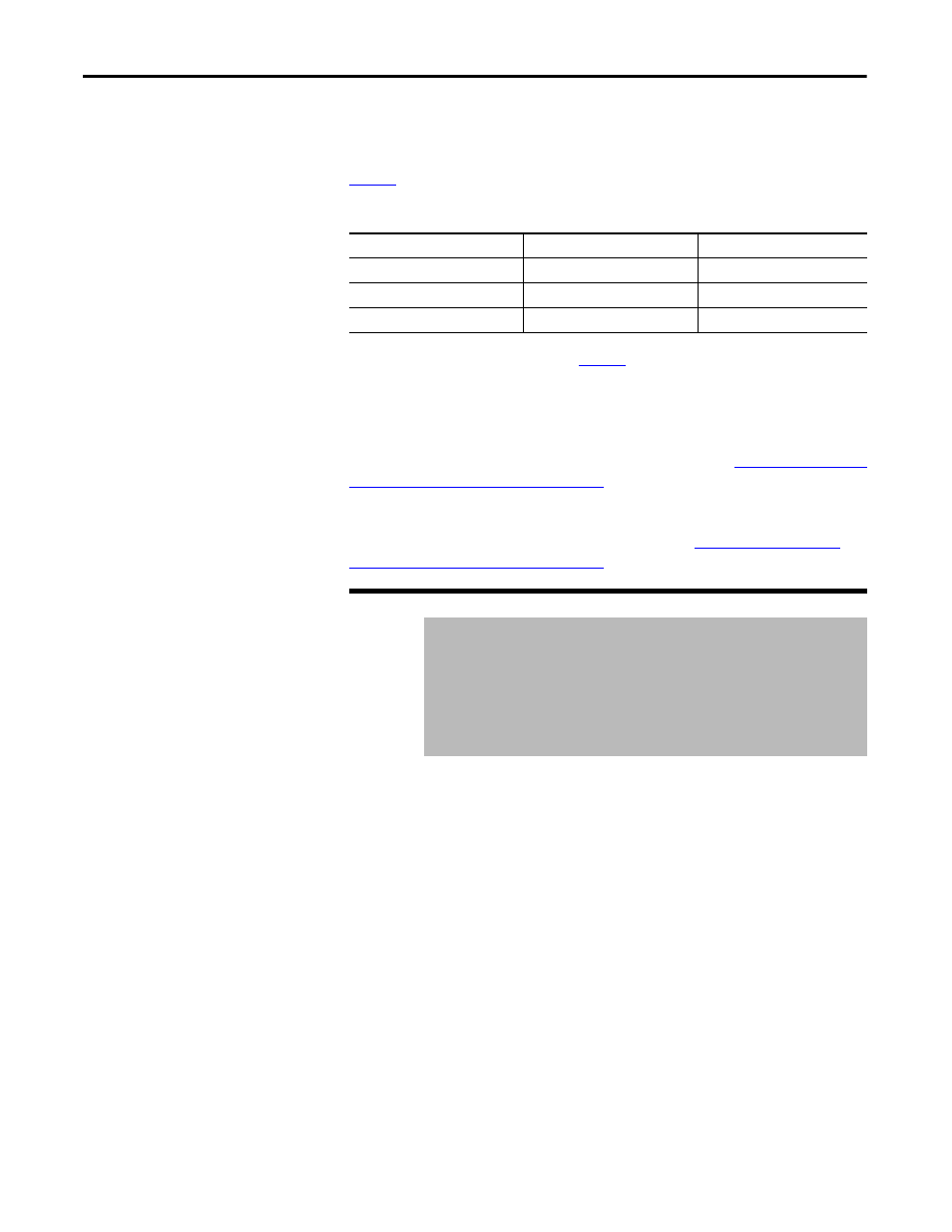
The usable range and default for this parameter depends on the operational mode
of the analog output, which in turn depends both on the capabilities of the analog
output hardware and the current value of parameter Analog Out Config (340).
describes the details for usable range and default.
Table 6 - Appl Analog Output (31) usable range and default
The value in the Default column of
is in effect when the drive powers up.
This parameter value is not stored in non-volatile memory.
For frame 3 drives (firmware version 1.x), the user-configurable analog output
hardware is located on the optional Standard I/O Board. This parameter is not
usable if the optional Standard I/O Board is not present. See
Description (Frame 3 Only) on page 27
for terminal block assignments.
For frame 4 drives (firmware version 2.x), the user-configurable analog output
hardware is located on the Combined I/O Board. See
Description (Frame 4 Only) on page 29
for terminal block assignments.
Selects how rectifier sequencing operates.
Mode
Usable Range
Default
0...10V (unipolar)
0.000...10.000V
0.000V
-10...10V (bipolar)
-10.000...10.000V
0.000V
4...20 mA
0.000...20.000 mA
0.000 mA
32
Rctfr Config
Range:
0 = Run at Start
1 = Run at Power Up
2 = Manual Control
3 = Diode Rectifier
Default:
0
Access:
1
Path: Monitor > Application
See also:
30
0
= The precharge is closed and voltage regulation is enabled when the
inverter is requested to start.
1
= The precharge is closed and voltage regulation is enabled when power is
turned on.
2
= The closing of the precharge and enabling of voltage regulation is
controlled by some other device writing into inverter Appl Digital Out
(30).
3
= Rectifier consists of a diode bridge. This mode is for engineering use only.