Combined i/o board description (frame 4 only), Digital inputs, Figure 11 - combined i/o board (frame 4) – Rockwell Automation Liqui-Flo V2.0 AC Drive User Manual
Page 29
Rockwell Automation Publication D2-3518-3 - May 2013
29
Chapter 2
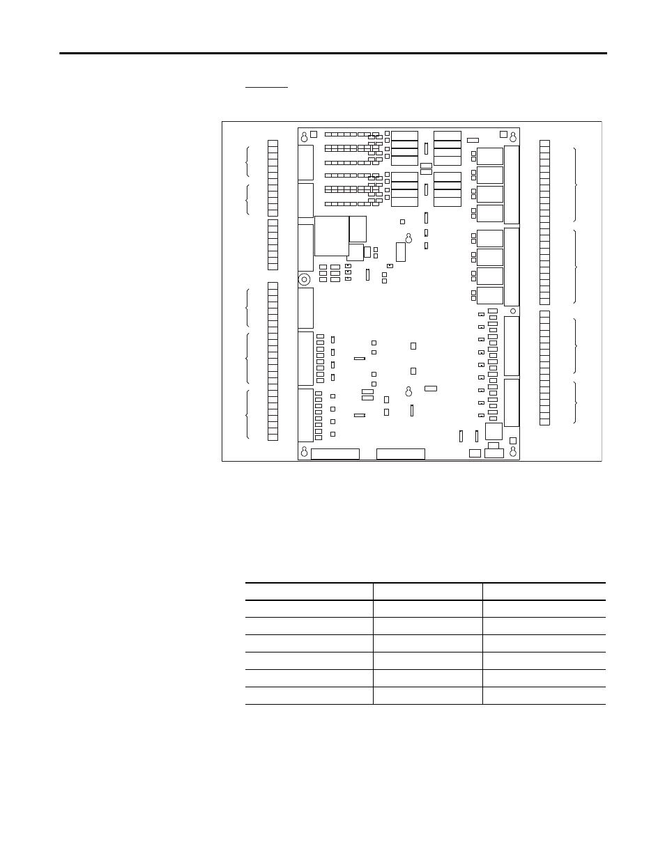
Combined I/O Board
Description (Frame 4 Only)
shows terminal block locations on the Combined I/O Board.
Figure 11 - Combined I/O Board (Frame 4)
Digital Inputs
The combined I/O board provides hardware for six user-configurable digital
inputs, using connector positions designated DI3...DI8. The following table
shows the correspondence between the digital input and the inverter parameter
used to configure it.
The states of all six user-configurable digital inputs are visible in inverter
parameter Dig In Status (216).
The digital inputs that use connector positions DI1 and DI2 on the combined
I/O board are not user-configurable. The status of these two digital inputs are
visible in rectifier parameter Dig In Status (216).
5
1
2
3
4
5
1
7
6
TB4
3
2
4
7
6
8
9
TB3
1
2
6
3
4
5
6
7
8
9
10
2
11
12
TB2
1
4
3
5
10
8
7
9
12
11
TB1
DI 6
DI 24V-
DI COM 2
DI 8
DI 7
DI 2
DI 24V-
DI 24V+
DI 5
DI 4
DI COM 1
DI 3
DI 24V+
DI 1
GATEKILL -
GATEKILL +
DIGITAL
OUTPUT
2
DO 8 NO
DO 8 COM
DO 3 NC
DO 8 NC
DO 7 NO
DO 7 COM
DO 7 NC
DO 6 NO
DO 6 COM
DO 6 NC
DO 5 NO
DIGITAL
OUTPUT
1
DO 4 COM
DO 5 COM
DO 5 NC
DO 4 NO
DO 3 NO
DO 4 NC
DO 3 COM
DO 1 NO
DO 2 COM
DO 2 NO
DO 2 NC
DO 1 NC
DO 1 COM
DIGITAL
INPUT
2
DIGITAL
INPUT
1
+12V
1
AO 1-
OUTPUT
ANALOG
AO 3-
6
AO 4-
8
AO 4+
7
AO 2-
AO 3+
5
4
AO 2+
3
2
INPUT
ANALOG
ENCODER
INPUT
TB9
AO 1+
1
AI 4-
AI 4+
8
7
AI 3-
AI 3+
6
5
AI 2-
AI 2+
4
3
B+
TB8
AI 1+
AI 1-
2
1
B-
6
A+
3
A-
5
4
COMMON 2
G1
1
TEMPSW RCT
TEMPSW INV
VOLTAGE
GRID
SHUNT TRIP
3
PRECHARGE FB
7
TB10
5
6
SW 24V
4
G3
5
TB7
CNTRL PWR
PRECHARGE OUT 2
1
G2
3
VOLTAGE
LINE
L2
3
TB6
L3
5
TB5
L1
1
Inverter Parameter Number
Inverter Parameter Name
Connector Position Designator
361
Digital In1 Sel
DI3
362
Digital In2 Sel
DI4
363
Digital In3 Sel
D15
364
Digital In4 Sel
DI6
365
Digital In5 Sel
DI7
366
Digital In6 Sel
DI8