Rockwell Automation 6000 PowerFlex Medium Voltage Variable Frequency Drive Commissioning Manual User Manual
Page 69
Rockwell Automation Publication 6000-IN007A-EN-P - October 2014
69
No-load Test
Chapter 4
P091
Skip Frequency 1 Upper Limit
0
ON
0
75
R&D
P092
Skip Frequency 2 Lower Limit
0
ON
0
75
R&D
P093
Skip Frequency 2 Upper Limit
0
ON
0
75
R&D
P113
Flying Start-Initial Output Voltage
Percentage (%)
5
ON
0
100
R&D
P114
Flying Start-Current Comparison Delay For
Motor Speed Search (ms)
1000
ON
0
5000
R&D
P115
Flying Start-Current Threshold For Successful
Motor Speed Search
5
ON
0
100
R&D
P198
HECS Rated Current (A)
0
ON
0
5000
Setup
Set value according to the Electrical Drawings
P199
Motor Rated Current (A)
0
ON
0
5000
Setup
Set value according to the customer motor nameplate data
P205
Motor Uab Voltage Scaling Factor Correction
199.99
ON
0
199.99
R&D
P206
Motor Uac Voltage Scaling Factor Correction
199.99
ON
0
199.99
R&D
P213
Output Short-Circuit Fault Threshold
180
ON
0
199.99
Setup
P216
High-Frequency Output Over Current
Threshold
120
ON
0
199.99
Setup
P224
Output Voltage Deviation Fault Threshold
80
ON
0
199.99
Setup
Set to 120 for Control System Check. Set to 80 afterwards
P252
Motor In Stopping Condition Threshold
1
ON
0
100
R&D
P253
Motor Coast Stop Time
10
ON
0
10000
R&D
P259
Frequency Command Analog Offset
0
ON
-100
199.99
R&D
P260
Frequency Command Analog Scaling Factor
100
ON
0
199.99
Setup
P262
Frequency Command Source Selection
0: Digital
1: Analog
0
OFF
0
1
Setup
P335
Analog Output #1 Scaling Factor
100
ON
0
199.99
Setup
DCS display the output voltage proportion coefficient and can be
changed as the customer operation request from 0...200%
(2)
P339
Analog Output #2 Scaling Factor
100
ON
0
199.99
Setup
DCS display the output current proportion coefficient and can be
changed as the customer operation request from 0...200%
(2)
P352
Rated Frequency HMI Display Integer Part
50
ON
0
75
Setup
P355
Motor Voltage HMI Display Integer Part
10000
ON
0
16384
Setup
Local display voltage correction coefficient, the value must be
done according to the rating of the inverter output voltage
setting.
For example: if the output is 3 kV, then set P355 = 3000
P358
Actual Frequency HMI Display Integer Part
50
ON
0
75
Setup
P361
Motor Current HMI Display Integer Part
0
ON
0
5000
Setup
Normally P361 = P199
P399
Deceleration Time (s)
300
ON
0
3276
Setup
Default value is 300 s. Set according to customer specification
The time from 50...0 Hz after stopping the motor
P401
Acceleration Time (s)
200
ON
0
3276
Setup
Default value is 200 s. Set according to customer specification
The time from 0...50 Hz after starting the motor
P413
Frequency Command Lower Limit
0
ON
-16384
16384
R&D
P414
Frequency Command Deadband Upper Limit
0.49
ON
0
100
R&D
P415
Frequency Command Upper Limit
16384
ON
-16384
16384
R&D
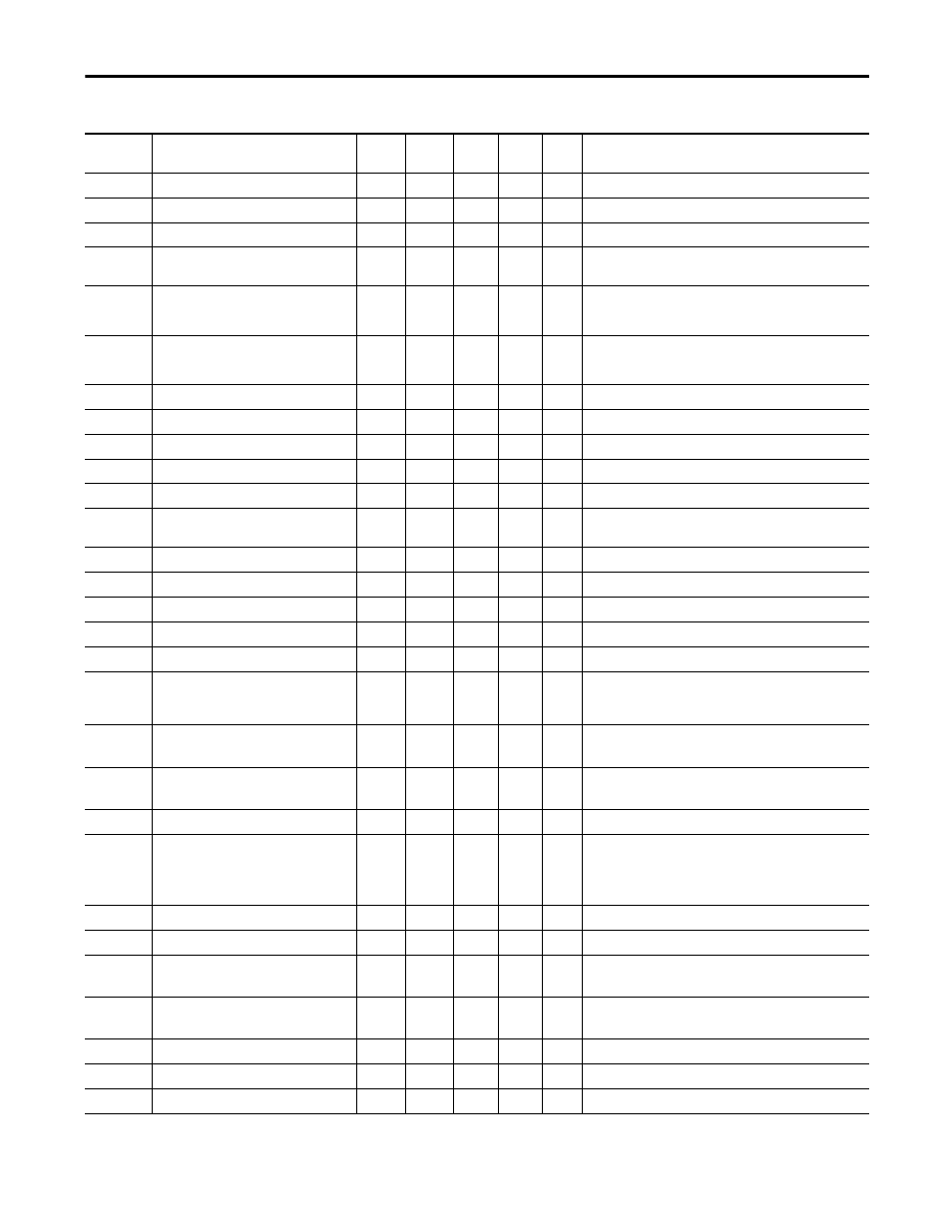
Table 12 - Setup and R&D Parameters (Continued)
P
Parameter
Description
Default
Modify
Root
(1)
Min.
Value
Max.
Value
Login
Level
Instruction