Rockwell Automation 6000 PowerFlex Medium Voltage Variable Frequency Drive Commissioning Manual User Manual
Page 34
34
Rockwell Automation Publication 6000-IN007A-EN-P - October 2014
Chapter 3
Commissioning
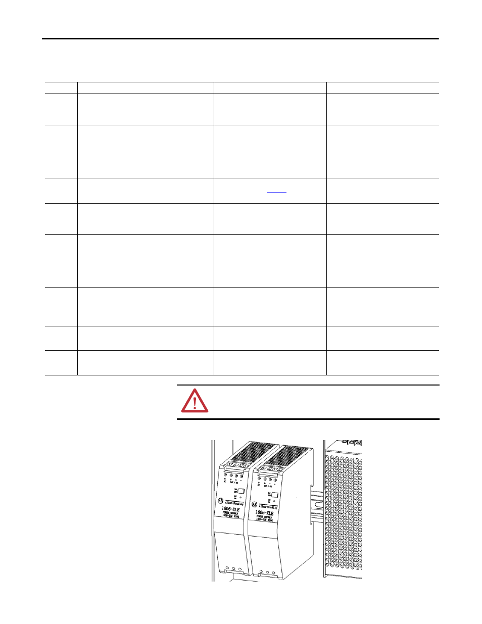
Figure 16 - AC/DC Power Supplies
Table 8 - Energize Control Circuit Sequence
Item
Before Closing Breaker
After Closing Breaker
Comments
Close
Breaker Q1
Verify that the input voltage at the Q1 circuit breaker is
AC220V (1 is L, 3 is N). Verify output is not shorted (2 and 4).
Verify OPEN state (5 and 6).
Verify that the output voltage is AC220V (2 is L, 4
is N). Verify CLOSED state (5 and 6).
Q1 connects customer-supplied control power to
the control circuit (UPS).
Start UPS
(Press ON
button)
Before pressing the ON button, withdraw the Type I UPS
power plug from the power receptacle (XS2). Verify that the
input voltage of the XS2 receptacle is AC220V. Verify that the
PE connection of the XS2 receptacle is properly grounded.
Plug the UPS into the receptacle. Press and hold the ON
button for 3 seconds to turn on the UPS (all status lights on
the UPS will be green).
Verify that UPS operates normally and that the
UPS output is AC220V. The output of the UPS is
connected to the input of Q2 and Q3. The UPS
output voltage can be checked at the input of Q2
or Q3 (1 is L, 3 is N).
UPS feeds control power to the circuits supplied
by the Q2 and Q3 circuit breakers.
Close
Breaker Q2
Verify that the input voltage at the Q2 circuit breaker is
AC220V (1 is L, 3 is N). Ignore if done in “Start UPS” step.
Verify output is not shorted (2 and 4).
Verify that the input voltage of power supplies is
AC220V (L-N). Refer to
. Verify that the
PLC, HMI, and Control Unit power up.
Q2 connects control power directly to AC/DC
power supplies (G1, G2, and G3), PLC, HMI, and
Control Unit
Close
Breaker Q3
Verify that the input voltage at the Q3 circuit breaker is
AC220V (1 is L, 3 is N). Ignore if done in “Start UPS” step.
Verify output is not shorted (2 and 4). Verify OPEN state (5
and 6).
Verify that the output voltage is AC220V (2 is L, 4
is N). Verify CLOSED state (5 and 6). Verify that
the PLC I/O status lights and control relay red
indicating lights illuminate.
Q3 connects control power to PLC I/O and control
relays.
Close
Breaker Q4
Control power is fed from the isolation transformer tertiary
winding for the Q4 circuit breaker, therefore not present for
this test. A two pole breaker is supplied for lower power
drives (220V powered auxiliary fans). A three pole breaker is
supplied for higher power drives (380V power auxiliary
fans). Verify open status (1 and 2) and output not shorted (2
and 4).
Verify closed status (1 and 2).
Q4 connects control power from isolation
transformer tertiary winding to bottom-
mounted auxiliary fans (6).
Close
Breaker Q5
Control power is fed from the isolation transformer tertiary
winding for the Q5 circuit breaker, therefore not present for
this test. Verify open status (1 and 2) and output not shorted
(2 and 4).
Verify closed status (1 and 2).
Q5 connects back-up control power from
isolation transformer tertiary winding to switch
to the control circuit (UPS) if the main (customer-
supplied) control power is lost.
Close
Breaker Q6
Verify that the input voltage at the Q6 circuit breaker is
AC220V (1 is L, 3 is N). Verify output is not shorted (2 and 4).
Verify that the output voltage is AC220V (2 is L, 4
is N). Verify that the LV Door pilot lights
illuminate.
Q6 connects control power to door mounted pilot
lights and spare relays for DCS.
Close
Breaker Q7
Verify that the input voltage at the Q7 circuit breaker is
AC220V (1 is L, 3 is N). Verify output is not shorted (2 and 4).
Verify that the output voltage is AC220V (2 is L, 4
is N). Verify that the Isolation Transformer
temperature monitor powers up.
Q7 connects control power to isolation
transformer temperature monitor
ATTENTION: The following should be opened successively when the control
power is switched off: Q5, Q4, Q3, Q2 and UPS; opening Q1 is not necessary
when the control power is not disconnected.
N
N L
L