Control system check setup, Simulate closed input circuit breaker, Energize control circuit – Rockwell Automation 6000 PowerFlex Medium Voltage Variable Frequency Drive Commissioning Manual User Manual
Page 32
32
Rockwell Automation Publication 6000-IN007A-EN-P - October 2014
Chapter 3
Commissioning
Control System Check Setup
Simulate Closed Input Circuit Breaker
Energize Control Circuit
Before beginning this process, ensure that the customer's control power supply
breaker is closed and control power is available.
Control power voltage used in the control circuit is nominally 220V and referred
to in the example. The control circuit can directly accommodate other widely
used voltages of 230V and 240V also. If 110V or 120V is the control power
voltage supplied by the customer, a control power transformer is supplied in the
LV control cabinet to step up the customer supplied control power to 220V
(
). This must be specified at time of order.
Q1, Q2, Q3, Q5, and Q6 miniature circuit breaker designations are located in
the LV Control Cabinet (
). The Q4 and Q7 miniature circuit breaker
designations are located in the LV Control panel of the Isolation Transformer
Cabinet (
). Refer to the Electrical Drawings.
Test points indicated in the instructions are at the circuit breaker terminals, not at
the terminal blocks.
Circuit breaker device designation labels (Q1, Q2, etc.) are affixed to the device
mounting surfaces.
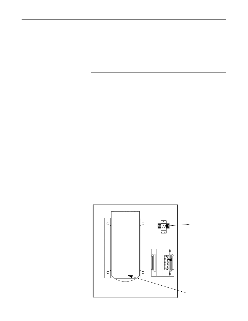
Figure 13 - UPS and CPT Mounting Plate (Top View)
IMPORTANT
The “normal” operating mode is for the input circuit breaker to be closed.
Install a temporary jumper (X1-117, X1-119) in the LV Control Cabinet to
simulate operating the system in “normal” mode (input circuit breaker closed)
to allow the Control System Check process to proceed.
Refer to Electrical Drawings.
XS2 Receptacle
Optional
Control Power
Transformer
UPS
REAR
FRONT