Electrical installation inspection, Power cabling, Electrical installation inspection power cabling – Rockwell Automation 6000 PowerFlex Medium Voltage Variable Frequency Drive Commissioning Manual User Manual
Page 22
22
Rockwell Automation Publication 6000-IN007A-EN-P - October 2014
Chapter 2
Preparation and Inspection
Electrical Installation Inspection
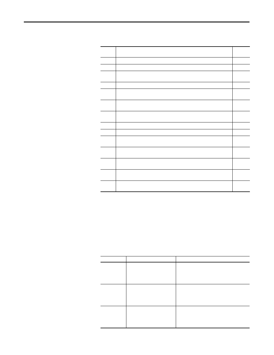
Power Cabling
Trace the power cabling from termination point to termination point while
examining the cable and its routing for mechanical damage, sharp bend radiuses
and sources of induced noise and heat. The power cabling must be is sufficiently
braced to contain the cabling in the event of a ground fault. Color coding is used
to indicate the phase orientation of the drive.
Sequence
Task
Reference
Document
1
Verify that medium voltage cables are separated at least 30 cm from the control cables
2
Verify that all secondary control wiring use shielded cables
3
Verify that input and output medium voltage cables specifications meet the stated
insulation requirements
Electrical
Drawings
4
Verify that input and output medium voltage cables have attached nameplates
5
Verify the diameter of control power cables comply with the drawings
Electrical
Drawings
6
Verify that the electrical safety circuit wiring between the input circuit breaker and the drive
is shielded and only the end at the drive side is grounded
7
Verify the wiring between the DCS and the drive is shielded and only the end the drive side is
grounded
8
Verify that the user-provided ground cable is ≥50 mm
2
9
Verify the isolation transformer’s primary input voltage matches the system primary voltage
10
Verify that the customer motor specifications match the drive voltage and current
capabilities
11
Verify that the isolation transformer’s input side wiring is correct
Electrical
Drawings
12
Verify that the motor output side wiring is correct
Electrical
Drawings
13
Verify all external control wiring is terminated correctly and to the proper terminal blocks
Electrical
Drawings
14
Verify torque on incoming line power cable and outgoing motor power cable terminations
Electrical
Drawings
Table 6 - Color Coding
Color
Incoming Line Side
Outgoing Motor Side
Yellow
L11 (A Phase) Line Cable Terminal
U Phase:
• Power Module Bus
• VSB Input Cable
• Motor Cable Termination
• Motor Cable Connection to Power Module Bus
Green
L12 (B Phase) Line Cable Terminal
V Phase:
• Power Module Bus
• VSB Input Cable
• Motor Cable Termination
• Motor Cable Connection to Power Module Bus
Red
L13 (C Phase) Line Cable Terminal
W Phase:
• Power Module Bus
• VSB Input Cable
• Motor Cable Termination
• Motor Cable Connection to Power Module Bus