Connect the insulation meter – Rockwell Automation 6000 PowerFlex Medium Voltage Variable Frequency Drive Commissioning Manual User Manual
Page 27
Rockwell Automation Publication 6000-IN007A-EN-P - October 2014
27
Preparation and Inspection
Chapter 2
10.
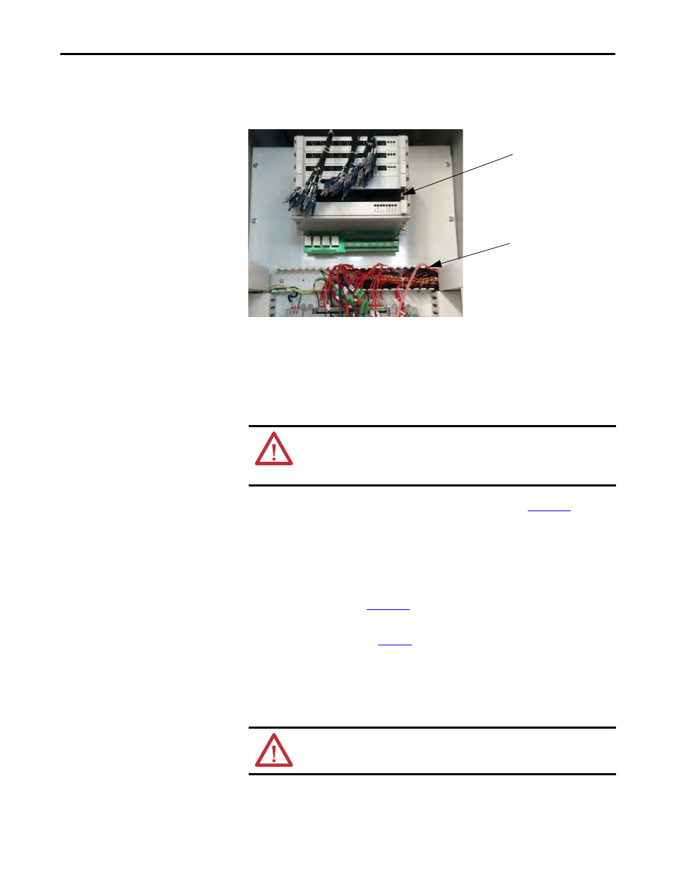
Remove the Analog Interface board and disconnect all of the terminals
from the Control Unit.
Figure 9 - Back of Control Unit
Connect the Insulation Meter
1.
Connect the red wire from the insulation meter to the U Phase and the
black wire to the grounding bus.
2.
Use jumper wires to make the connections as shown in
.
The jumper wires must be rated for greater than 5 kV or must maintain
sufficient clearance to any metal surface.
3.
If the Megger has a lower voltage setting (normally 500V or 1000V), apply
that voltage for 5 seconds as a precursor for the higher voltage rating. This
may limit the damage if there is a problem. If the reading is very high, apply
the test voltage per
4.
Perform a Megger test with the insulation meter voltage set according to
the voltages shown in
for 1 minute and record the result.
The test should produce a reading greater than the minimum values listed
below. If the test results produced a value lower than these values start
segmenting the drive system down into smaller components and repeat the
test on each segment to identify the source of the ground fault.
Analog Interface Board
location on Control Unit
Control Unit terminals
ATTENTION: Verify the drive and any connected equipment is clear of
personnel and tools prior to commencing the Megger test. Barricade off
any open or exposed conductors. Conduct a walk-around inspection
before commencing the test.
ATTENTION: Discharge the Megger prior to disconnecting it from the
equipment.