Interconnection review – Rockwell Automation 6000 PowerFlex Medium Voltage Variable Frequency Drive Commissioning Manual User Manual
Page 20
20
Rockwell Automation Publication 6000-IN007A-EN-P - October 2014
Chapter 2
Preparation and Inspection
Interconnection Review
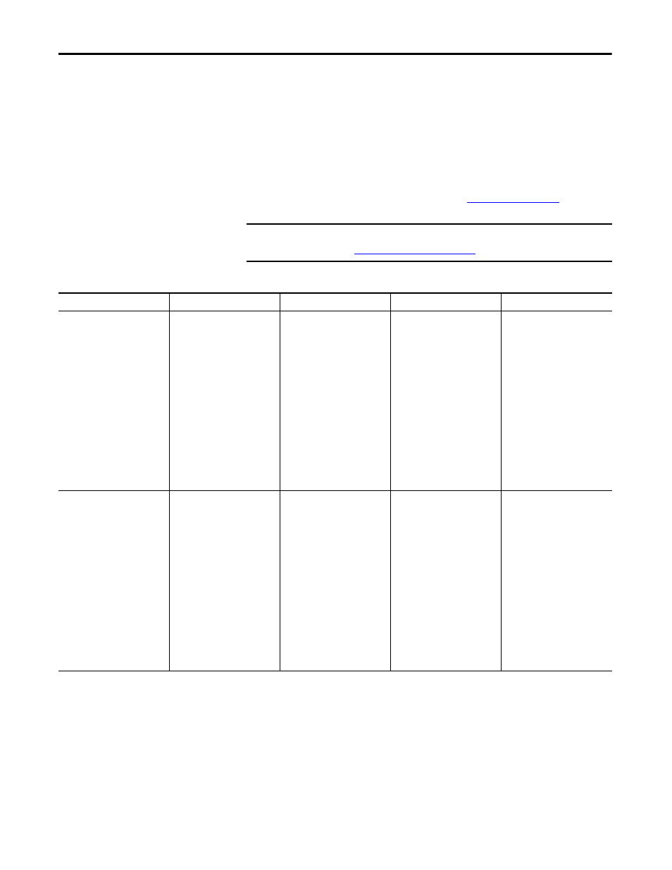
The interconnection checklist summarizes the required items to review to
validate the reconnection of power, ground, and control cables between cabinets
within the drive system, that were disconnected for shipment. Power and control
cables that pass from one cabinet to another are bundled in the appropriate
cabinet. These cables are connected for system test at the factory but
disconnected and coiled up for shipment. If this interconnection work was done
by the contractor, use this checklist to review and ensure the work was done
correctly. If the interconnection work was not done by the contractor, the scope
of work required to be performed is described in
.
IMPORTANT
Check torque on all power and ground cable connections per specifications
listed in
Torque Requirements on page 81
.
Table 5 - Interconnection Review Checklist
Bypass Cabinet (if supplied)
Isolation Transformer Cabinet
Power Module Cabinet
Low Voltage Control Cabinet
Front Inspection
Verify the braided ground
connection to adjacent cabinet(s)
is properly installed
Review the braided ground
connection to adjacent cabinet
Verify line and load power
cables from Isolation Transformer
Cabinet are properly connected
Verify all control wires per
Electrical Drawing
Verify the braided ground
connection to adjacent cabinet(s)
is properly installed
Review all isolation
transformer secondary wiring
from Power Module cabinet
(2 sets)
Verify that the shields of all
of the system’s connecting wires
are properly grounded
Verify all control wires per
Electrical Drawing
– Cables are run in LV cable
sections along front and
back of cabinet
Verify the braided ground
connection to adjacent cabinet(s)
is properly installed
Verify that the shields of all
of the system’s connecting wires
are properly grounded
Review load power cable
connection from Isolation
Transformer Cabinet
Verify Voltage Sensing
Board power cables from Isolation
Transformer Cabinet are properly
installed
Verify control signal wiring
bundles from LV Control cabinet
to LV panel in Isolation
Transformer cabinet and LV panel
in the Bypass Cabinet (if supplied)
are routed correctly
Rear Inspection
Fixed Mounted Power
Module:
Verify all isolation
transformer secondary windings
from Power Module Cabinet are
properly connected (1 set)
Drawout Power Module:
Verify all isolation
transformer secondary windings
from Power Module Cabinet are
properly connected (3 sets)
Verify all power supply
cables for main cooling fans for
Isolation Transformer Cabinet are
properly connected(3 sets)