Ground the switch – Rockwell Automation 1783-BMxxx Stratix 5700 Ethernet Managed Switches User Manual User Manual
Page 62
62
Rockwell Automation Publication 1783-UM004E-EN-P - June 2014
Chapter 2 Switch Installation
Ground the Switch
Use at least 4 mm
2
(12 AWG) wire to connect to the external grounding screw.
The ground lug is not supplied with the switch. You can use one of the these
options:
• Single ring terminal
• Two single ring terminals
To ground the switch to earth ground, follow these steps. Be sure to follow any
grounding requirements at your site.
1. Use a Phillips screwdriver or a ratcheting torque screwdriver with a Phillips
head to remove the ground screw from the front panel of the switch.
Store the ground screw for later use.
2. Use the manufacturer’s guidelines to determine the wire length to be
stripped.
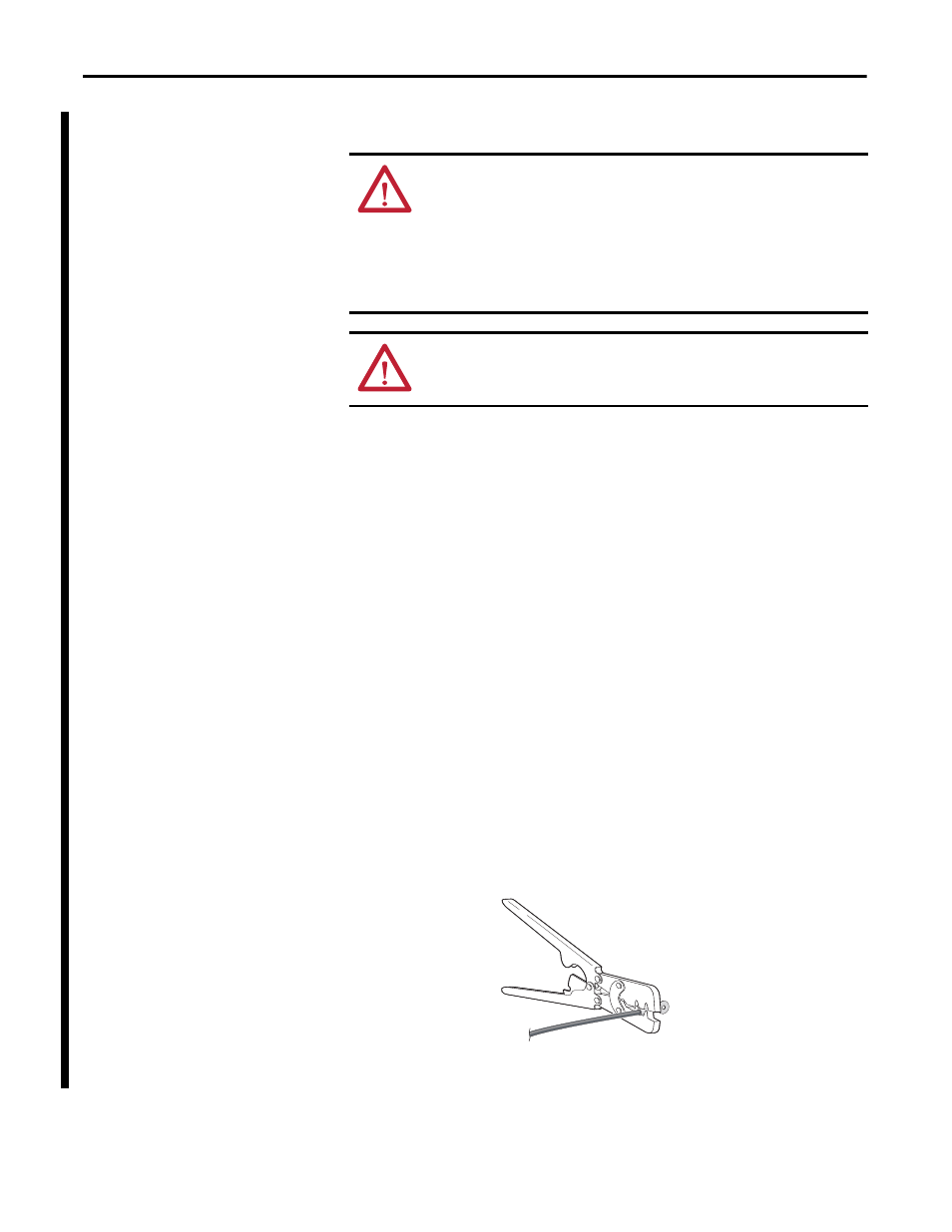
3. Insert the ground wire into the ring terminal lug and use a crimping tool to
crimp the terminal to the wire.
If you are using two ring terminals, repeat this action for the second ring
terminal.
4. Slide the ground screw through the terminal.
ATTENTION: This equipment must be grounded. Never defeat the ground
conductor or operate the equipment in the absence of a suitably installed
ground conductor. Contact the appropriate electrical inspection authority or an
electrician if you are uncertain that suitable grounding is available.
This equipment is intended to be grounded to comply with emission and immunity
requirements. Make sure that the switch functional ground lug is connected to
earth ground during normal use.
ATTENTION: To make sure that the equipment is reliably connected to earth
ground, follow the grounding procedure instructions and use a suitable ring
terminal lug, such as Thomas & Bett part number 10RCR or equivalent.
32273-M