Attach the poe power connector, Install an sfp module (optional) – Rockwell Automation 1783-BMxxx Stratix 5700 Ethernet Managed Switches User Manual User Manual
Page 46
46
Rockwell Automation Publication 1783-UM004E-EN-P - June 2014
Chapter 2 Switch Installation
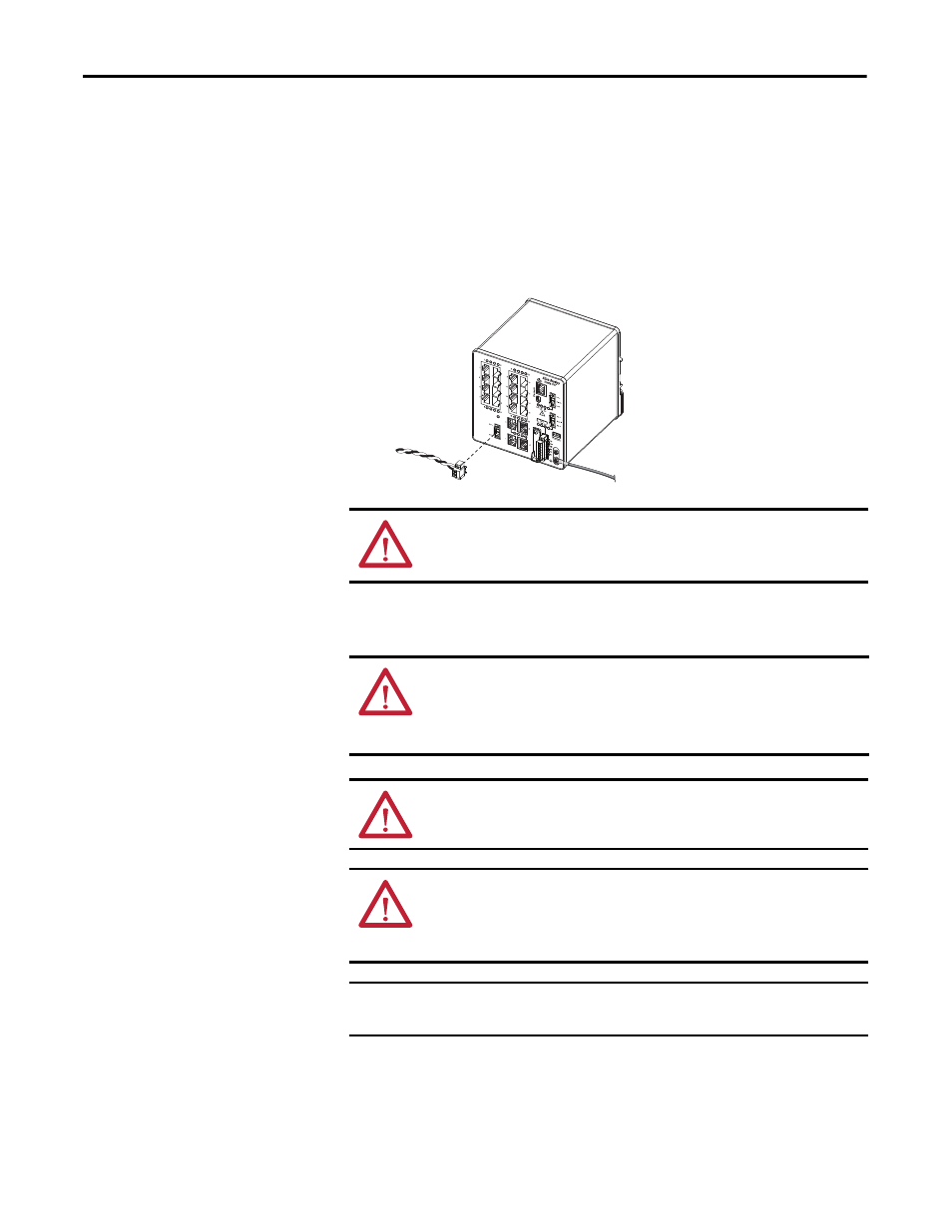
Attach the PoE Power Connector
This procedure applies only to switches with PoE ports.
1. Insert the power connector into the DC input terminal block on the
switch front panel.
2. Use a screwdriver to tighten the captive screws on the sides of the power
connector.
Install an SFP Module (optional)
On switch catalog numbers that support communication over fiber optic cable,
SFP modules are inserted into SFP module slots on the front of the switch. These
field-replaceable modules provide the uplink optical interfaces, send (TX) and
receive (RX).
ATTENTION: Exposure to some chemicals can degrade the sealing properties of
materials used in the relay. Periodically inspect the relay and check for any
degradation.
WARNING: When you insert or remove the small form-factor pluggable (SFP)
optical transceiver while power is on, an electrical arc can occur. This could
cause an explosion in hazardous location installations.
Be sure that power is removed or the area is nonhazardous before proceeding.
ATTENTION: Use only Rockwell 1783-SFP100FX, 1783-SFP100LX,
1783-SFP1GSX, or 1783-SFP1GLX SFPs.
ATTENTION: We strongly recommend that you do not install or remove the SFP
module with fiber optic cables attached to it because of the potential damage
to the cables, the cable connector, or the optical interfaces in the SFP module.
Disconnect all cables before removing or installing an SFP module.
IMPORTANT
Installing and removing an SFP module can shorten its useful life. Do not
remove and insert SFP modules more often than is absolutely necessary.
PoE Input Pwr
48VDC
, 1.2A