Rockwell Automation 1783-BMxxx Stratix 5700 Ethernet Managed Switches User Manual User Manual
Page 39
Rockwell Automation Publication 1783-UM004E-EN-P - June 2014
39
Switch Installation Chapter 2
Use at least 4 mm
2
(12 AWG) wire to connect to the external grounding screw.
The ground lug is not supplied with the switch. You can use one of the these
options:
• Single ring terminal
• Two single ring terminals
To ground the switch to earth ground, follow these steps. Be sure to follow any
grounding requirements at your site.
1. Use a Phillips screwdriver or a ratcheting torque screwdriver with a Phillips
head to remove the ground screw from the front panel of the switch.
Store the ground screw for later use.
2. Use the manufacturer’s guidelines to determine the wire length to be
stripped.
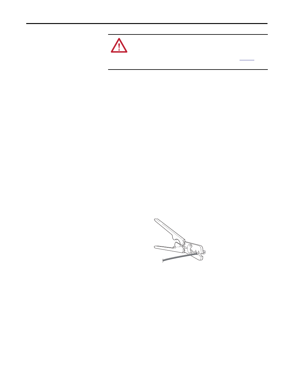
3. Insert the ground wire into the ring terminal lug and use a crimping tool to
crimp the terminal to the wire.
If you are using two ring terminals, repeat this action for the second ring
terminal.
4. Slide the ground screw through the terminal.
ATTENTION: For proper grounding, you must always connect the power supply
functional-ground screw when connecting the power supply. You must provide
an acceptable grounding path for each device in your application. For more
information on proper grounding guidelines, refer to publica
Industrial Automation Wiring and Grounding Guidelines.
32273-M