Rockwell Automation 900-TC32 Digital Temperature Controllers, Series B User Manual
Page 199
Publication 900-UM007D-EN-E - January 2011
Parameter Adjustments & Application Considerations
4-63
Transfer Output Scaling
• Reverse scaling is possible by configuring the Transfer Output
Lower-Limit parameter larger than the Transfer Output Upper-Limit
parameter. If the Transfer Output Lower-Limit and Transfer Output
Upper-Limit parameters are configured to the same value when 4…20
mA is configured, the transfer output will output continuously a 0% (4
mA) signal.
• If the SP, SP during SP ramp, or PV is selected as the Transfer Output
Type, the Transfer Output Lower-Limit and Transfer Output
Upper-Limit parameters will follow the values configured for the
respective parameter’s Upper- and Lower-Limits concerning changes in
the Upper- and Lower-Limits of the SP limiter and temperature units.
• If the MV for heating or MV for cooling is selected as the Transfer
Output Type, the Transfer Output Lower-Limit and Transfer Output
Upper-Limit parameters will be initialized to 100.0 and 0.0, respectively,
when a switch is made between standard control and heating/cooling
control using the Standard or Heating/Cooling parameter.
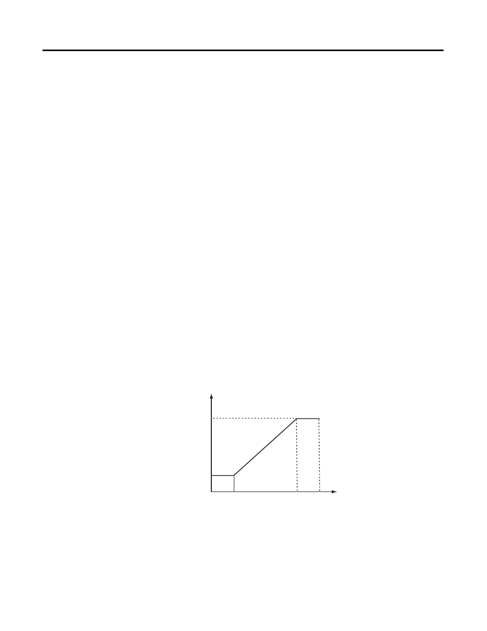
• When the linear current type is configured as 4…20 mA, the transfer
output Upper-Limit is configured to 90.0, and the transfer output
Lower-Limit is configured to 10.0 is shown in the following graph (refer
to Figure 4.136).
• For scaling from 0.0…100.0%, 0.0% will be the output for
−5.0…0.0,
and 100% will be the output for 100.0…105.0.
Figure 4.136 —
When the Linear Current Output Type is Set to 4 to 20 mA
100
90
10
0
20
4
Output current (mA)
MV (%)
Transfer output
lower limit
Transfer output
upper limit