Rockwell Automation 284G ArmorStart - User Manual User Manual
Page 295
Safety I/O Module and TÜV Requirements
F-3
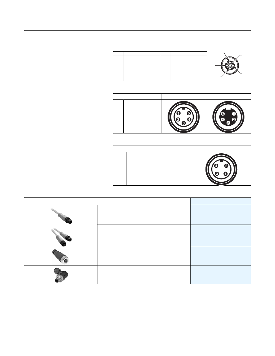
Micro Connector Pin Assignments
Mini Connector Pin Assignments
Power Configuration Pin Assignments
ArmorBlock Guard I/O Recommended Compatible Cables and Connectors
➊ Replace symbol with 1 (1 m), 2 (2 m), 5 (5 m), or 10 (10 m) for standard cable length.
Face View Pinout
Female
Input Configuration
Output Configuration
Pin
Signal
Pin
Signal
1
2
3
4
5
Test Output n+1
Safe Input n+1
Input Common
Safe Input n
Test Output n
1
2
3
4
5
Output +24V DC Power
Output n+1 (sinking)
Output Power Common
Output n (sourcing)
Output Power Common
Face View Pinout
Male
Female
Pin
Signal
1
2
3
4
5
Drain
V+ (Red)
V- (Black)
CAN_H (White)
CAN_L (Blue)
Face View Pinout
Male
Pin
Signal
1
2
3
4
Output +24V DC Power (Red)
Input +24V DC Power (Green)
Input Power Common (White)
Output Power Common (Black)
5
4
3
1
2
Description
Cat. No.
DC Micro (M12) Male Cordset
889D-F4HJ-
➊
DC Micro Style Patchcord
889D-F4HJDM-
➊
M12 Terminal Chamber, Straight Male
871A-TS4-DM
M12 Terminal Chamber, Right Angle Male
871A-TR4-DM