Rockwell Automation 284G ArmorStart - User Manual User Manual
Page 199
Troubleshooting
10-11
The Auto Restart feature provides the ability for the drive to
automatically perform a fault reset followed by a start attempt without
user or application intervention. This allows remote or unattended
operation. Only certain faults are allowed to be reset. Certain faults
(Type 2) that indicate possible drive component malfunction are not
resettable.Caution should be used when enabling this feature, since
the drive will attempt to issue its own start command based on user
selected programming.
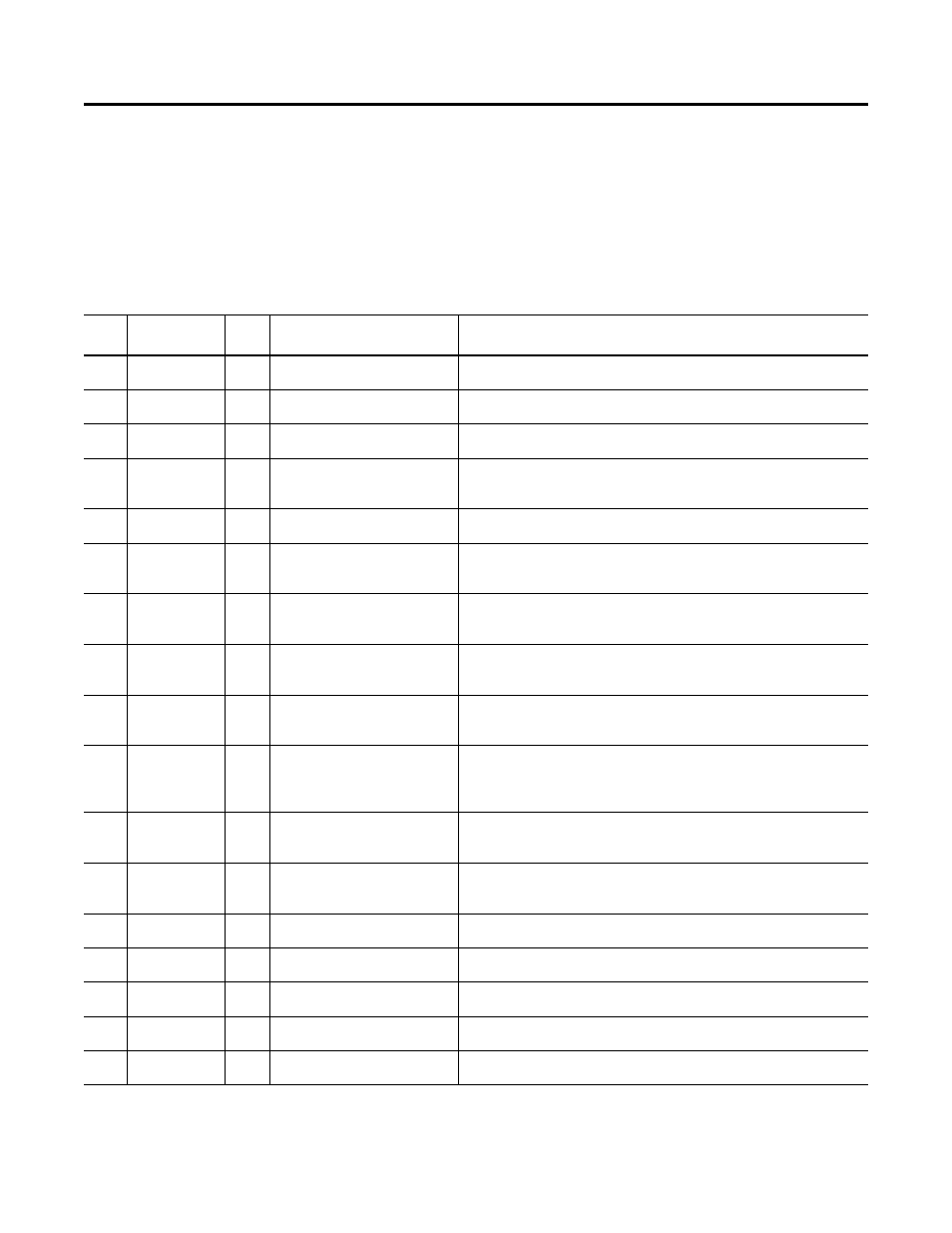
Table 10.5 Fault Types, Descriptions, and Actions
No.
Fault
Type
➊
Description
Action
F2
Auxiliary Input
1
Auxiliary input interlock is open.
1.
Check remote wiring.
2.
Verify communications.
F3
Power Loss
2
DC bus voltage remained below
85% of nominal.
3.
Monitor the incoming AC line for low voltage or line power interruption.
4.
Check input fuses.
F4
UnderVoltage
1
DC bus voltage fell below the
minimum value.
5.Monitor the incoming AC line for low voltage or line power interruption.
F5
OverVoltage
1
DC bus voltage exceeded maximum
value.
6.Monitor the AC line for high line voltage or transient conditions. Bus overvoltage
can also be caused by motor regeneration. Extend the decel time or install
dynamic brake option.
F6
Motor Stalled
1
Drive is unable to accelerate motor.
7.Increase Parameter 139…167 (Accel Time x) or reduce load so drive output
current does not exceed the current set by Parameter 189 (Current Limit 1).
F7
Motor Overload
1
Internal electronic overload trip
8.
An excessive motor load exists. Reduce load so drive output current does not
exceed the current set by Parameter 133 (Motor OL Current).
9.
Verify Parameter 184 (Boost Select) setting
F8
Heatsink OvrTmp
1
Heatsink temperature exceeds a
predefined value.
10.
Check for blocked or dirty heat sink fins. Verify that ambient temperature
has not exceeded 40
°
C.
11.
Replace internal fan.
F12
HW OverCurrent
2
The drive output current has
exceeded the hardware current
limit.
12.Check programming. Check for excess load, improper programming of
Parameter 184 (Boost Select), DC brake volts set too high, or other causes of
excess current.
F13
Ground Fault
2
A current path to earth ground has
been detected at one or more of the
drive output terminals.
13.Check the motor and external wiring to the drive output terminals for a
grounded condition.
F33
Auto Rstrt Tries
Drive unsuccessfully attempted to
reset a fault and resume running for
the programmed number of
Parameter 192 (Auto Rstrt Tries).
14.Correct the cause of the fault and manually clear.
F38
F39
F40
Phase U to Gnd
Phase V to Gnd
Phase W to Gnd
2
A phase to ground fault has been
detected between the drive and
motor in this phase
.
15.
Check the wiring between the drive and motor.
16.
Check motor for grounded phase.
17.
Replace starter module if fault cannot be cleared.
F41
F42
F43
Phase UV Short
Phase UW Short
Phase VW Short
2
Excessive current has been detected
between these two output terminals.
18.
Check the motor and drive output terminal wiring for a shorted condition.
19.
Replace starter module if fault cannot be cleared.
F48
Params Defaulted
2
The drive was commanded to write
default values to EEPROM.
20.
Clear the fault or cycle power to the drive.
21.
Program the drive parameters as needed.
F63
SW OverCurrent
2
Programmed Parameter 198 (SW
Current Trip) has been exceeded.
22.Check load requirements and Parameter 198 (SW Current Trip) setting.
F64
Drive Overload
2
Drive rating of 150% for 1 min. or
200% for 3 sec. has been exceeded.
23.Reduce load or extend Accel Time.
F70
Power Unit
2
Failure has been detected in the
drive power section.
24.
Cycle power.
25.
Replace starter module if fault cannot be cleared.
F80
SVC Autotune
The autotune function was either
cancelled by the user or failed.
26.Restart procedure.