Rockwell Automation 284G ArmorStart - User Manual User Manual
Page 223
Specifications
A-13
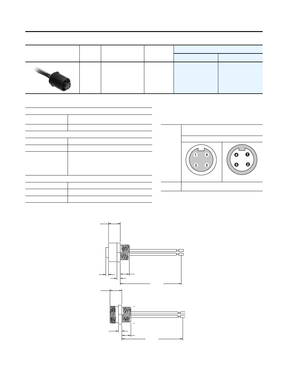
Table 1.C Power Receptacles (Male and Female)
Specifications
Pinout and Color Code
Approximate Dimensions
Dimensions in millimeters (inches). Dimensions are not intended to be used for manufacturing purposes and are subject to change.
Pin Count
Assembly Rating
Color Code
Cat. No.
Female
Male
0
0
4-pin
10 AWG, 600V, 25 A
B
280-M35F-M1
280-M35M-M1
Mechanical
Receptacle Shell Material
Black Anodized Aluminum (female) and Zinc DieCast,
Black E-Coat (male) or 316 Stainless Steel
Insert
Black PVC
Electrical
Contacts
Copper Alloy with Gold over Nickel Plating
Cable Rating
600V AC/DC
Assembly Rating
4-pin: 10 AWG, 600V @ 25 A
Symmetrical Amps RMS Fault 65 kA when used with
Class CC, T, or J type fuses or
100 A circuit breaker
Environmental
Enclosure Type Rating
IP67, NEMA 4; 1200 psi washdown
Certifications
UL Listed (File No. E318496, Guide PVVA)
Standards Compliance
UL 2237
Face View Pinout
10 AWG, 600V @ 25 A
4-pin
Female
Male
Color Code
(B)
1 Black
3 Red
2 Green/Yellow Extended PIN
4 White
280-M35F-M1
280-M35M-M1
45.26
(1.782)
7.62 +/-2.54
(0.30 +/- 0.10)
11.89 (0.468)
6.35 (0.25)
11.89 (0.468)
6.35 (0.25)
51.61
(2.032)
1000
(39.37)
1000
(39.37)