Programming the 1756-controllogix, I/o mapping – Rockwell Automation 284G ArmorStart - User Manual User Manual
Page 158
6-8
Explicit Messaging on DeviceNet™
Programming the
1756-ControlLogix
I/O Mapping
The following example will use the standard distributed motor
controller and the factory default input and output assembly of 160
and 161. Refer to Appendix B for additional assembly formats. The
default input and output assembly will again be used in the following
example.
Note: The addressing is different between the SLC 1747 and
ControlLogix 1756 program. It is important that the user
understand how to create and use “tags” in order to properly
follow the example. Please see the RSLogix™ 5000
programming manual for additional help with defining tags.
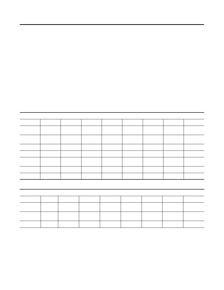
The tables below list the data configuration for the ControlLogix
platform and include the tag name as used in the example program.
Table 6.9
Example ControlLogix Input Addressing (Produced Assembly)
)
Table 6.10 Example ControlLogix Output Address (Consumed Assembly)
)
Instance 161 Default Produced Standard Distributed Motor Controller
Byte 0
Bit 7
Bit 6
Bit 5
Bit 4
Bit 3
Bit 2
Bit 1
Bit 0
Address
Local:1:I.
Data[1].7
Local:1:I.
Data[1].6
Local:1:I.
Data[1].5
Local:1:I.
Data[1].4
Local:1:I.
Data[1].3
Local:1:I.
Data[1].2
Local:1:I.
Data[1].1
Local:1:I.
Data[1].0
Tag Name
—
—
—
—
—
—
Status_
warning
Status_
tripped
Data
reserved
reserved
reserved
Ready
Running Rev
Running Fwd
Warning
Tripped
Byte 1
Bit 15
Bit 14
Bit 13
Bit 12
Bit 11
Bit 10
Bit 9
Bit 8
Address
Local:1:I.
Data[1].15
Local:1:I.
Data[1].14
Local:1:I.
Data[1].13
Local:1:I.
Data[1].12
Local:1:I.
Data[1].11
Local:1:I.
Data[1].10
Local:1:I.
Data[1].9
Local:1:I.
Data[1].8
Tag Name
—
140M On
—
—
—
—
—
—
Data
reserved
reserved
User In 5
User In 4
User In 3
User In 2
User In 1
User In 0
Instance 160 Default Consumed Standard Distributed Motor Controller
Byte 0
Bit 7
Bit 6
Bit 5
Bit 4
Bit 3
Bit 2
Bit 1
Bit 0
Address
Local:1:O.
Data[1].7
Local:1:O.
Data[1].6
Local:1:O.
Data[1].5
Local:1:O.
Data[1].4
Local:1:O.
Data[1].3
Local:1:O.
Data[1].2
Local:1:O.
Data[1].1
Local:1:O.
Data[1].0
Tag Name
—
—
—
—
—
Control_fault
Reset
—
—
Data
reserved
reserved
reserved
reserved
reserved
Fault Reset
Run Rev
Run Fwd