N o t e – ETC Echo Architectural Control Processor (ACP) v1.0.0 User Manual
Page 33
3
Programming
28
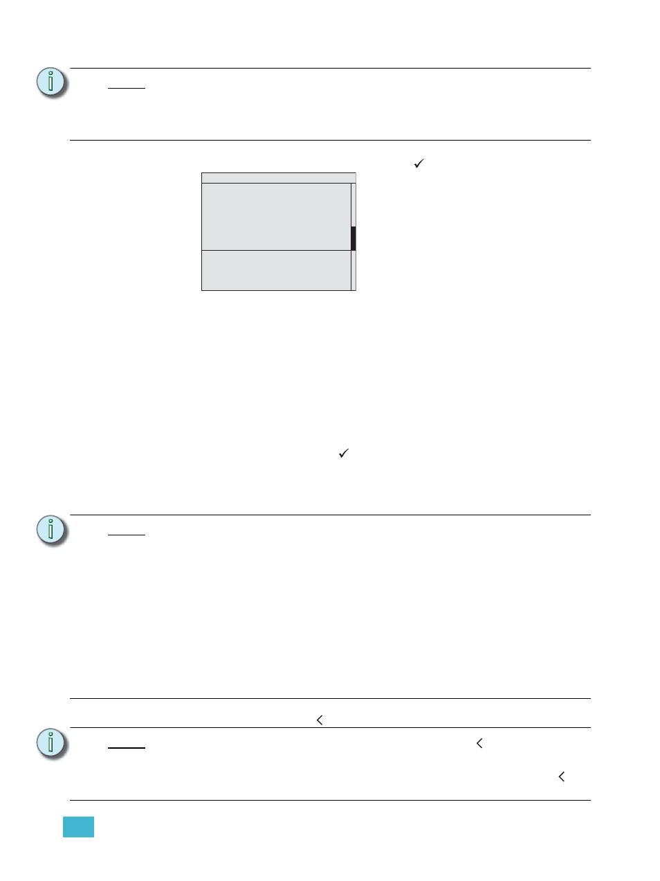
Step 4:
Scroll to “Mode” property and press enter (
). “Mode” displays for selection.
•
Reverse Phase and LED Smoothing Reverse modes display as a selectable
mode only when the “Module Type” is ELV or when using reverse phase
controlled module types such as the ELV10, HELV5, AELV5, EELV6.
•
Dimmer Doubled Mode when the rack type is DRd48 with an Auxiliary Rack
or the rack voltage is 240V, Dimmer Doubled is not displayed for selection.
•
When Dimmer Doubled Mode is selected, properties for Transformer Mode
and DMX Res are read only.
•
Fluorescent modes are abbreviated in the Dimmer Setup display, but are
displayed properly in the Mode selection display.
Step 5:
Scroll to select the firing mode for the selected dimmer from the available options
in the list then press enter (
). Changing the dimming firing mode
automatically changes the default settings for curve, threshold, voltage
regulation, minimum voltage and maximum voltage.
Step 6:
Continue through each of the available dimmer properties, modifying each
property only as needed.
Step 7:
Press the back button ( ) to return to the Dimming Setup menu.
N o t e :
Each module type has a default set of properties such as the firing mode, dimmer
curve, etc. When changing a module type, all dimmer properties for the specified
dimmer(s) also change to match the new module type property defaults. You may
edit the dimmer properties individually. Refer to
Dimmer Module Defaults, page 65
for a listing of standard dimmer properties.
N o t e :
The listing below identifies relatively important information when setting these
additional properties. Reference
for detailed
information about all dimmer properties.
• When the Voltage Reg: property is set to Off, the Max Scale Voltage property is
not displayed.
• When Dimmer Doubled is the selected firing mode, the DMX Res: property
automatically defaults to “Lo 8 bit”.
• Each dimmer must be assigned to a Space. By default, all dimmers are assigned
to Space 1. Spaces are created in the Arch Setup menu.
• By default, all Zones of Space 1 are assigned to the first 16 consecutive dimmers
in the same Space.
• By default, all Circuit numbers default to match the dimmer number.
• The circuit “Name” is a read only property.
N o t e :
When exiting the “Dimmer Setup” using the back button ( ), and the changes
made to dimmers / dimmer properties have affected the rack DMX input patch /
sACN input patch, a dialog will display requesting confirmation.
Select to fix the patch issues through the dialog or press the back button ( ) to
ignore the dialog and return to the “Dimming Setup” menu.
Mode
Normal
Dimmer Doubled
Switched
2/3 Wire Fluorescent
Always On
Off
4 Wire Fluorescent
DALI
Reverse Phase
LED Smoothing Fwd
LED Smoothing Reverse
Reference
for
detailed information regarding standard
dimmer firing modes.