Festo Электромотор MTR-DCI User Manual
Page 47
3. Installation
3-5
Festo P.BE-MTR-DCI-IO-EN en 1209d
If non-assigned plug connectors are touched, there is a
danger that damage may occur to the MTR-DCI or to other
parts of the system as a result of ESD (electrostatic dis-
charge). Place protective caps on unused connections in
order to prevent such discharges.
The plug connectors of the following Festo cables have been
designed so that, when inserted and screwed tight, or if fitted
with protective covers, the connections on the MTR-DCI will
comply with protection class IP54.
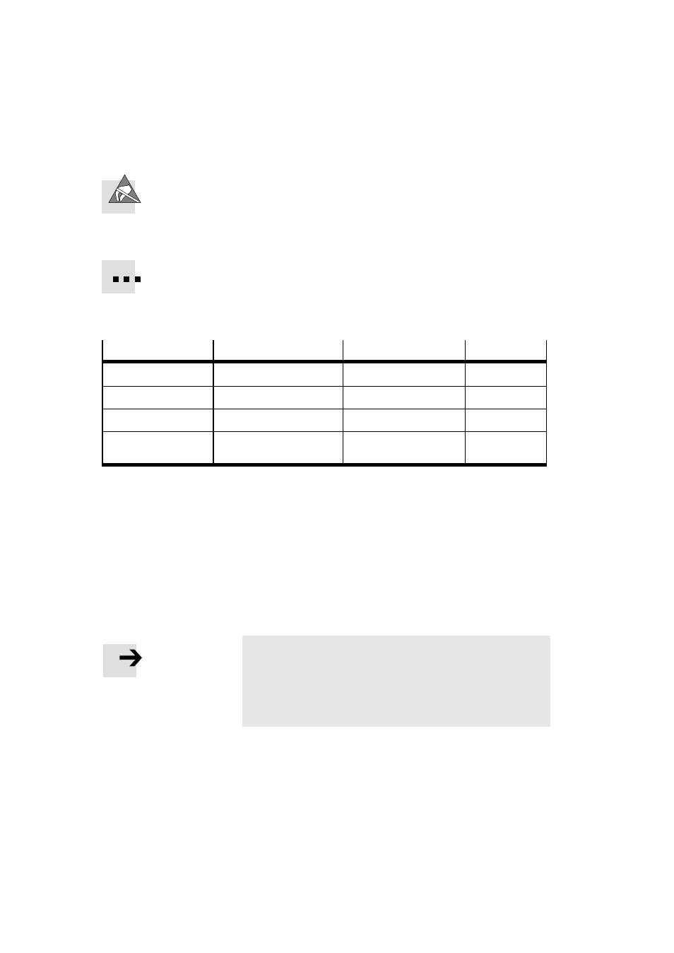
Connection
Cable
Designation
Length [m]
Voltage supply
Power supply cable
KPWR-MC-1-SUB-9HC
2.5 / 5 / 10
I/O control
Pilot line
KES-MC-1-SUB-9HC
2.5 / 5 / 10
Serial interface
Programming cable
KDI-MC-M8-SUB-9
2.5
Homing Switch
If necessary, connecting
cable with screw-type lock
KM8-M8-GSGD
0.5 / 1 / 2 / 5
Tab. 3/2: Overview of cables (accessories)
In order to guarantee compliance with the IP protection class:
•
Seal unused M8 connections with ISK-M8 protective caps
(accessories).
•
Hand-tighten the union nuts/locking screws of the plugs.
Observe the permissible tightening torques specified in
the documentation for the lines and plugs used.
Note
•
Lay all moveable motor and sensor cables free of bends
and free of mechanical stress, if necessary, in a drag
chain.
•
Observe the maximum specified cable lengths.