Ag Leader Versa Users Manual User Manual
Page 268
254
Firmware Version 5.4
• Response Threshold
Determines where the control channel switches between
using Actuator Response 1 and Actuator Response 2
speed settings. Leaving all other actuator control
settings at the default value and making a small
adjustment to this setting is usually all that is required to
fine-tune system performance. The default setting is 4.
- Decreasing this value will have the overall effect of
speeding up actuator response.
- Increasing this value will have the overall effect of
slowing actuator response.
• Allowable Error
Determines the percent of error that is allowed prior to
the product control system making any flow rate changes. 2% - 3% is the normal dead band setting range.
- Too low of a setting value can cause the product control system to continually hunt for the target
application rate.
- Too high of a setting will cause excessive product application error.
• Shaft Speed Cal
Calibration number representing the pulses that equal one revolution of the rate control metering system.
• Max Conveyor Speed
Setting determines the maximum RPM of the conveyor that controls product distribution to the application
point.
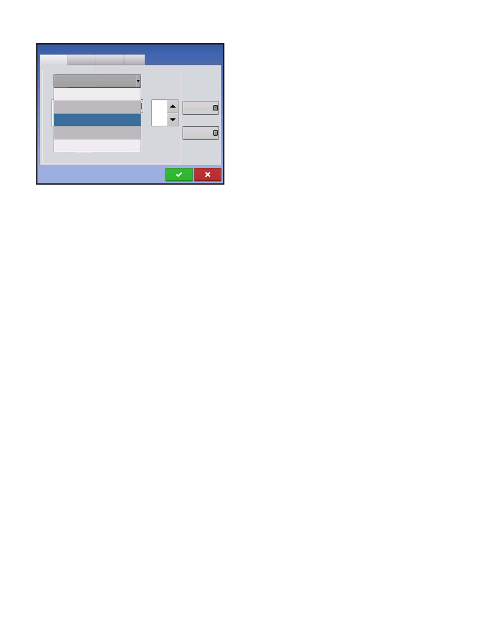
• Actuator/Clutch Configuration
Selecting one of the three available actuator/clutch settings: [Single Bin Actuator], [Multiple Bin Actuator,
Main Only], [Multiple Bin Actuator, Main + Channel] from the Control Valve Configuration drop-down menu
(above) determines specific behavior of the actuators/clutches on zero rate.
Channel 1
Channel 2
Channel 3
Control Valve Configuration
Auxiliary
Single Bin Actuator
Servo
PWM
Single Ben Actuator
Multiple Bin Actuator, Main Only
Multiple Bin Actuator, Main + Channel
Allowable
Error
2 %
Shaft Speed
Calibration
180 pls/rev
Max Metering
Speed
100 rpm
Strip Till Control